Broan 124 Handleiding
Bekijk gratis de handleiding van Broan 124 (8 pagina’s), behorend tot de categorie Heater. Deze gids werd als nuttig beoordeeld door 160 mensen en kreeg gemiddeld 4.4 sterren uit 3 reviews. Heb je een vraag over Broan 124 of wil je andere gebruikers van dit product iets vragen? Stel een vraag
Pagina 1/8
1
READ AND SAVE
THESE INSTRUCTIONS
MODELS 120, 124 & 128
REGISTER HEATERS
MODELOS 120, 124 Y 128
CALENTADORES DE REJILLA
LEA Y CONSERVE
ESTAS INSTRUCCIONES
WARNING
1.ALL ELECTRICAL WORK MUST BE DONE IN ACCOR-
DANCEWITH LOCAL OR NATIONAL ELECTRICAL
CODE AS APPLICABLE.FOR SAFETY,THIS PROD-
UCT MUST BE GROUNDED. IF YOU ARE UNFAMIL-
IAR WITH METHODS OF INSTALLING ELECTRICAL
WIRING, SECURE THE SERVICES OF A QUALIFIED
ELECTRICIAN.
2.WHEN WIRING, SERVICING OR CLEANING THIS
UNIT, TURN OFF POWER AND LOCK OUT SERVICE
PANEL. FAILURE TO DO SO COULD ALLOW OTHERS
OR THERMOSTAT TO TURN ON POWER UNEX-
PECTEDLY WHICH MAY CAUSE FATAL ELECTRICAL
SHOCK.
3.To avoid electrical shock:
• DO NOT install unit in a tub or shower enclosure or
any location where it may come in contact with water.
• NEVER place a switch where it can be reached from
a tub or shower.
4.DO NOT install this unit in an area where chemicals or
other flammables are stored or used. Explosion and fire
may result.
CAUTION
1.This product may ONLY be installed horizontally in a wall.
DO NOT MOUNT IN ANY OTHER POSITION.
2.Install heater at least 6" from floor or any adjacent vertical
surface.
3.DO NOT locate heater behind a door, furniture, drapes,
etc., where the air flow to the unit would be restricted.
4.Provide heater with an appropriately-rated electrical
circuit to prevent tripped breakers or blown fuses (See
chart below.)
5.DO NOT CONNECT HEATER TO DIMMER SWITCH
OR SPEED CONTROL.
6.To avoid motor bearing damage and noisy and/or unbal-
anced impellers, keep drywall spray, construction dust,
etc., off power unit.
7.Please read specification label on product for further
information and requirements.
PLANNING
This heater is intended to be used to supply supplemental
heat from a wall location in new or existing construction.
The heater can be operated using the Broan Model 86
Line-Voltage Thermostat from a wall location. Purchase the
control separately.
Plan to supply the heater with proper line voltage and ap-
propriate power cable.
NOTE: Power can be tapped from a nearby circuit depend-
ing on the heater wattage required and the amperage rating
of the circuit.
Heater can be converted to half-wattage to avoid overload-
ing such circuits.
The table below lists the ratings for each model.
INSTALLER: Leave This Manual With The Homeowner. HOMEOWNER: Use and Care Information on Page 3.
INSTALADOR: Deje este manual con el dueño de casa. DUEÑO DE CASA: Información del uso y mantenimiento en la página 3.
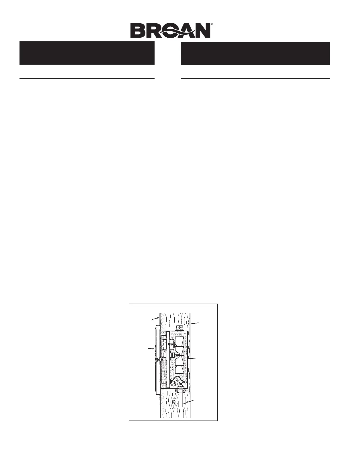
FIG. 1
DRYWALL/
PARED DE
YESO
GRILLE/
REJILLA
WALL
STUD/
VIGA DE
LA PARED
HEATER
HOUSING/
CAJA DEL
CALENTA-
DOR
POWER
CABLE/
CABLE
DE EN-
ERGIA
ADVERTENCIA
1.TODO EL TRABAJO ELECTRICO DEBE REALIZARSE
DE ACUERDO CON LOS CODIGOS ELECTRICOS
LOCALESY/ONACIONALESCORRESPONDIENTES.
PARA SU SEGURIDAD, ESTE PRODUCTO DEBE
SER CONECTADO A TIERRA. SI USTED NO ESTA
FAMILIARIZADO CON LOS METODOS DE INSTALACION
DEL CABLEADO ELECTRICO, OBTENGA LOS
SERVICIOS DE UN ELECTRICISTA COMPETENTE.
2.AL HACER EL CABLEADO, LIMPIEZA O DAR SERVICIO
A ESTA UNIDAD, DESCONECTE LA POTENCIAY
ASEGURE EL PANEL DE SERVICIO. EL NO HACERLO
PUEDE HACER POSIBLE QUE OTRAS PERSONAS O
EL TERMOSTATO ACTIVE LA ENERGIA EN FORMA
INESPERADA, LO QUE PUEDE CAUSAR UN GOPE
ELECTRICO MORTAL.
3.Para evitar descarga eléctrica:
* NO instale la unidad en una bañera o recinto de ducha,
ni en ningún lugar donde pueda entrar en contacto con
el agua.
* NUNCA coloque un interruptor en un lugar que pueda
ser alcanzado desde una bañera o ducha.
4.NO instale esta unidad en un área donde se almacenen o
usen productos químicos u otros productos inflamables.De
lo contrario, pueden producirse explosiones e incendios.
CUIDADO
1.Este producto SOLAMENTE se puede instalar horizontal-
mente en una pared. NO LO MONTE EN NINGUNA OTRA
POSICION.
2.Instale el calentador por lo menos a 15,24 cm (6 pulg.) de
distancia del piso o de alguna superficie vertical adyacente.
3.NO COLOQUE el calentador detrás de una puerta,
muebles, cortinas, etc., donde el flujo de aire a la unidad
se encuentre restringido.
4.Proporcione un circuito eléctrico de capacidad nominal al
calentador, a fin de impedir la desconexión de disyuntores
o quemado de fusibles. (Véase el diagrama abajo).
5.NO CONECTE EL CALENTADOR A UN VARIADOR DE
LUZ O UN CONTROL DE VELOCIDAD.
6.Para evitar daños al cojinete del motor e impulsores
ruidosos y/o desequilibrados, mantenga la unidad de
energía alejada de rocíos de yeso, polvo de construcción,
etc.
7.Para más información y requisitos, lea la etiqueta de
especificación sobre el producto.
PLANIFICACION
Este calentador p1-ha sido diseñado para proporcionar calefacción adi-
cional desde una pared en una construcción nueva o una p1-ya existente.
El calentador se puede poner en funcionamiento desde una pared
usando el termostato de tensión de línea Broan Modelo 86. Adquiera
los controles en forma separada.
Planifique proporcionar al calentador la tensión de línea y cable de
energía eléctrica apropiados.
NOTA: La energía se puede tomar de un circuito cercano, lo que
dependerá del vatiaje requerido del calentador y amperaje nominal
del circuito.
El calentador se puede convertir a mitad de vatiaje para evitar sobre-
cargar dichos circuitos.
IMPORTANT INSTRUCTIONS
READ ALL INSTRUCTIONS BEFORE
INSTALLING OR USING THIS HEATER.
To reduce the risk of fire, electric shock, or injury to persons,
observe the following:
1. Use this unit only in the manner intended by the manufacturer. If
you have questions, contact the manufacturer at the address or
telephone number listed in the warranty.
2. Before servicing or cleaning unit, switch power off at service
panel and lock the service disconnecting means to prevent
power from being switched on accidentally. When the service
disconnecting means cannot be locked, securely fasten a
prominent warning device, such as a tag, to the service panel.
3. Installation work and electrical wiring must be done by a
qualified person(s) in accordance with all applicable codes
and standards, including fire-rated construction codes and
standards.
4. When cutting or drilling into wall or ceiling, do not damage
electrical wiring and other hidden utilities.
5. This heater is hot when in use. To avoid burns, do not let bare
skin touch hot surfaces. Keep combustible materials, such as
furniture, pillows, bedding, papers, clothes, etc. and curtains at
least 3 feet (0.9 m) from the front of the heater.
6. Extreme caution is necessary when any heater is used by
or near children or invalids and whenever the heater is left
operating and unattended.
7. Do not operate any heater after it malfunctions. Disconnect
power at service panel and have heater inspected by a reputable
electrician before reusing.
8. Do not use outdoors.
9. To disconnect heater, turn controls to off, and turn off power
to heater circuit at main disconnect panel (or operate internal
disconnect switch, if provided).
10. Do not insert or allow foreign objects to enter any ventilation or
exhaust opening, as this may cause an electric shock or fire, or
damage the heater.
11. To prevent a possible fire, do not block air intakes or exhaust in
any manner.
12. A heater has hot and arcing or sparking parts inside. Do not use
it in areas where gasoline, paint, or flammable vapors or liquids
are used or stored.
13. Use this heater only as described in this
manual. Any other use not recommended by the
manufacturer may cause fire, electric shock, or
injury to persons.
14. Install heater at least 6 inches from floor or any
adjacent wall.
15. To avoid electrical shock: Do not install unit in a
tub or shower enclosure or any location where
it may come in contact with water. Never place
a switch where it can be reached from a tub or
shower.
16. This product may ONLY be installed horizontally
in a wall. Do not mount in any other position.
17. Do not connect heater to dimmer switch or
speed control.
18. This product must be grounded.
SAVE THESE INSTRUCTIONS
INSTRUCCIONES IMPORTANTES
LEA TODAS LAS INSTRUCCIONES ANTES DE
INSTALAR O USAR ESTE CALENTADOR.
Para reducir el riesgo de incendios, descargas eléctricas o lesiones
personales, observe las siguientes precauciones:
1. Use la unidad solo de la manera indicada por el fabricante. Si tiene
preguntas, comuníquese con el fabricante a la dirección o al número
telefónico que se incluye en la garantía.
2. Antes de dar servicio a la unidad o de limpiarla, interrumpa el suministro
eléctrico en el panel de servicio y bloquee los medios de desconexión
del servicio para evitar que la electricidad se reanude accidentalmente.
Cuando no sea posible bloquear los medios de desconexión del servicio,
fije firmemente una señal de advertencia (como una etiqueta) en un
lugar visible del panel de servicio.
3. El trabajo de instalación y el cableado eléctrico deben estar a cargo
de personal capacitado, de acuerdo con todos los códigos y normas
correspondientes, incluidos los códigos y normas de construcción
específicos sobre protección contra incendios.
4. Al cortar o perforar a través de la pared o del cielo raso, tenga cuidado
de no dañar el cableado eléctrico ni otros servicios ocultos.
5. Este calentador se calienta cuando se usa. Para evitar quemaduras,
no deje que la piel desnuda toque las superficies calientes. Mantenga
materiales combustibles como muebles, almohadas, ropa de cama,
papeles, ropa, etc., así como las cortinas, por lo menos a 3 pies (0.9
m) de la parte delantera del calentador.
6. Es necesario tener extremo cuidado cuando se use un calentador cerca
de niños o personas inválidas, y siempre que el calentador se deje
funcionando y sin atención.
7. No haga funcionar ningún calentador después de que presente una
falla. Desconecte la energía eléctrica en el panel de servicio y pida que
un electricista acreditado inspeccione el calentador antes de volverlo a
usar.
8. No lo use en exteriores.
9. Para desconectar el calentador, mueva los controles a la posición de
apagado y desconecte la energía eléctrica al circuito del calentador en
el panel de desconexión principal (o active el interruptor de desconexión
interna, si existe).
10. No inserte ni permita que objetos extraños entren en la abertura de
ventilación o de escape, pues esto puede ocasionar una descarga
eléctrica, un incendio o daños al calentador.
11. Para prevenir un posible incendio, no bloquee la
entrada o salida del aire de ninguna manera.
12. El calentador tiene piezas calientes y que pueden
generar arcos eléctricos o chispas en el interior. No
lo use en áreas donde se use o almacene gasolina,
pintura o vapores o líquidos flamables.
13. Use este calentador solamente como se describe en
este manual. Cualquier otro uso no recomendado
por el fabricante puede ocasionar un incendio, una
descarga eléctrica o lesiones a personas.
14. Instale el calentador por lo menos 6 pulg. desde el
piso o cualquier pared adyacente.
15. Para evitar golpe eléctrico: No instale la unidad en
una bañera o recinto de ducha. Nunca coloque un
interruptor en un lugar que pueda ser alcanzado
desde una bañera o ducha.
16. Este producto SOLAMENTE se puede instalar en
una pared. No lo monte en ninguna otra posicion.
17. No conecte el calentador a un variador de luz o
control de velocidad.
18. Este producto debe estar conectado a tierra.
GUARDE ESTAS INSTRUCCIONES
Product specificaties
| Merk: | Broan |
| Categorie: | Heater |
| Model: | 124 |
Heb je hulp nodig?
Als je hulp nodig hebt met Broan 124 stel dan hieronder een vraag en andere gebruikers zullen je antwoorden
Handleiding Heater Broan

10 Juli 2024
16 April 2024
16 April 2024
16 April 2024
16 April 2024
16 April 2024
16 April 2024
16 April 2024
16 April 2024
16 April 2024
Handleiding Heater
Nieuwste handleidingen voor Heater
14 Juli 2026
11 Juli 2026
9 Juli 2026
9 Juli 2026
9 Juli 2026
8 Juli 2026
8 Juli 2026
8 Juli 2026
7 Juli 2026
7 Juli 2026