Broan 114 Handleiding
Bekijk gratis de handleiding van Broan 114 (12 pagina’s), behorend tot de categorie Heater. Deze gids werd als nuttig beoordeeld door 52 mensen en kreeg gemiddeld 4.8 sterren uit 4 reviews. Heb je een vraag over Broan 114 of wil je andere gebruikers van dit product iets vragen? Stel een vraag
Pagina 1/12
Page 1
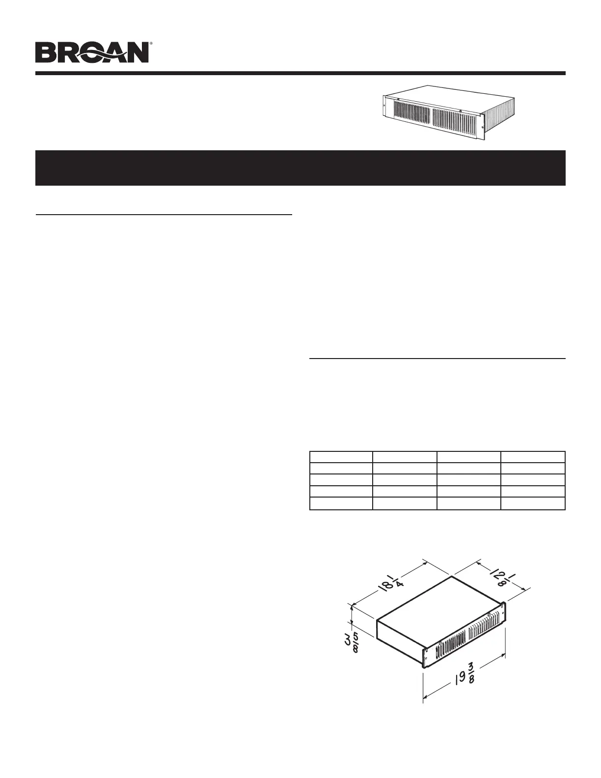
MODEL 114
KICKSPACE HEATER
Factory Wired 240/208 V.A.C.
READ AND SAVE THESE INSTRUCTIONS
VOLTS WATTS AMPS BTU/HR
240 1500 6.3 5120
208 1125 5.4 3840
120* 1500 12.5 5120
120* 750 6.3 2560
PLANNING
This heater is designed for installation in an enclosed space such
as under a counter or kickspace to provide warm, gentle heat at
the floor level. Reread Safety Notes 3 through 8 for guidelines in
planning the installation.
The Model 114 is factory wired for 240/208 V.A.C. operation. It offers
a choice of heat outputs and can be internally connected for multiple
wattages at different voltages shown in the table below.
All ratings are 1‑Phase, 60 Hertz.
*See “FIELD CONVERSION TO 120 V.A.C.” section.
IMPORTANT INSTRUCTIONS
READ ALL INSTRUCTIONS BEFORE
INSTALLING OR USING THIS HEATER.
To reduce the risk of fire, electric shock, or injury to persons,
observe the following:
1. Use this unit only in the manner intended by the manufacturer.
If you have questions, contact the manufacturer at the address
or telephone number listed in the warranty.
2. Before servicing or cleaning unit, switch power off at service
panel and lock the service disconnecting means to prevent
power from being switched on accidentally. When the service
disconnecting means cannot be locked, securely fasten a
prominent warning device, such as a tag, to the service panel.
3. Installation work and electrical wiring must be done by a
qualified person(s) in accordance with all applicable codes
and standards, including fire‑rated construction codes and
standards.
4. When cutting or drilling into wall or ceiling, do not damage
electrical wiring and other hidden utilities.
5. This heater is hot when in use. To avoid burns, do not let bare
skin touch hot surfaces. Keep combustible materials, such as
furniture, pillows, bedding, papers, clothes, etc. and curtains at
least 3 feet (0.9 m) from the front of the heater.
6. Extreme caution is necessary when any heater is used by
or near children or invalids and whenever the heater is left
operating and unattended.
7. Do not operate any heater after it malfunctions. Disconnect
power at service panel and have heater inspected by a
reputable electrician before reusing.
8. Do not use outdoors.
9. To disconnect heater, turn controls to off, and turn off power
to heater circuit at main disconnect panel (or operate internal
disconnect switch, if provided).
10. Do not insert or allow foreign objects to enter any ventilation or
exhaust opening, as this may cause an electric shock or fire, or
damage the heater.
11. To prevent a possible fire, do not block air intakes or exhaust in
any manner.
12. A heater has hot and arcing or sparking parts inside. Do not
use it in areas where gasoline, paint, or flammable vapors or
liquids are used or stored.
13. Use this heater only as described in this manual. Any other use
not recommended by the manufacturer may cause fire, electric
shock, or injury to persons.
14. To avoid electrical shock: Do not install unit in a tub or shower
enclosure or any location where it may come in contact with
water. Never place a switch where it can be reached from a tub
or shower.
15. Do not connect heater to dimmer switch or speed control.
16. Do not install heater upside down or sideways. Heater must be
located in the horizontal position.
17. Do not recess louvered face of the heater more than three inches
from the vertical face of any overhang (cabinet).
18. Provide this heater with a separate electrical circuit following
directions under “Wiring” section.
19. This product is equipped with a thermostat which may start it
automatically. Turn off power at service entrance before cleaning
or servicing.
20. This heater includes a visual alarm to warn that parts are getting
excessively hot. If the alarm lights are activated, immediately
turn the heater off and inspect for any objects on or adjacent
to the heater that may cause high temperatures.
21. This product must be grounded.
SAVE THESE INSTRUCTIONS
Cutout dimension: 18‑3/8” x 3‑5/8”
Product specificaties
| Merk: | Broan |
| Categorie: | Heater |
| Model: | 114 |
Heb je hulp nodig?
Als je hulp nodig hebt met Broan 114 stel dan hieronder een vraag en andere gebruikers zullen je antwoorden
Handleiding Heater Broan

10 Juli 2024
16 April 2024
16 April 2024
16 April 2024
16 April 2024
16 April 2024
16 April 2024
16 April 2024
16 April 2024
16 April 2024
Handleiding Heater
Nieuwste handleidingen voor Heater
14 Juli 2026
11 Juli 2026
9 Juli 2026
9 Juli 2026
9 Juli 2026
8 Juli 2026
8 Juli 2026
8 Juli 2026
7 Juli 2026
7 Juli 2026