AudioSource AMP 100 Handleiding
AudioSource Receiver AMP 100
Bekijk gratis de handleiding van AudioSource AMP 100 (4 pagina’s), behorend tot de categorie Receiver. Deze gids werd als nuttig beoordeeld door 43 mensen en kreeg gemiddeld 4.5 sterren uit 9 reviews. Heb je een vraag over AudioSource AMP 100 of wil je andere gebruikers van dit product iets vragen? Stel een vraag
Pagina 1/4
OWNER’S MANUAL
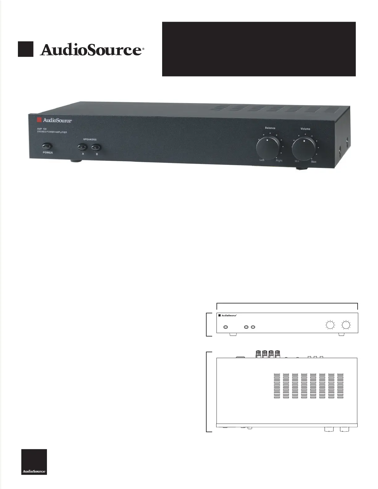
AMP 100
AudioSource®
13970 SW 72nd Ave
Portland, OR 97223
503.914.4688
ww
w.audiosource.net
AMP 100 Owner
’s Manual
Congratulations on your purchase of the AudioSource® AMP 100.
Please take a few moments to read this entire manual, and be sure to
retain this document for future reference. Please read and observe all
safety instructions detailed on page 2.
NOTE: If any part of this product is damaged or missing, please call your
dealer or AudioSource® directly at 1.877.715.5439 or 503.914.4688.
Please read your warranty and retain your receipt and original carton
for possible future use.
For more information about AudioSource® electronics, speakers and
accessories please visit www.audiosource.net
AMP 100
Home Audio Multi-Zone Stereo Power Amplifier
FEATURES:
Line 1 / Line 2 priority input switching
Line 2 auxiliary output
Speaker A/B switching
Front panel Balance and Volume controls
Signal sensing “Power On”
SPECIFICATIONS
Stereo (8 ohm):50W per channel, 20Hz ~ 20kHz, <1% THD+N
60W per channel, 1kHz, <1% THD+N
Stereo (4 ohm):60W per channel, 20Hz ~ 20kHz, <1% THD+N
75W per channel, 1kHz, <1% THD+N
Bridged Mono (8 ohm):160W, 1kHz, <1% THD+N
Frequency Response:10Hz ~ 30kHz, +0dB/ -3dB
Signal to Noise Ratio:100dBA below 50W output into 8 ohms
Channel Separation: 65dB @ 1kHz, referred to 50W output
into 8 ohms
Input Sensitivity:900mV input for rated 50W output
into 8 ohms
AC Power Consumption:500W maximum
Net Weight:9.6lbs / 4.4kgs
Gross Weight: 10.8lbs / 4.9kgs
2.9”
(74mm)
16.5”(419mm)
9.5”
(242mm)
Left
Right
Balance
Volume
SPEAKERS
AB
AMP 100
STEREO POWER AMPLIFIER
Min
Max
POWER
Product specificaties
| Merk: | AudioSource |
| Categorie: | Receiver |
| Model: | AMP 100 |
| Kleur van het product: | Zwart |
| Gewicht: | 4400 g |
| Breedte: | 419 mm |
| Diepte: | 242 mm |
| Hoogte: | 74 mm |
| Gewicht verpakking: | 4900 g |
| Aan/uitschakelaar: | Ja |
| Connectiviteitstechnologie: | Bedraad |
| Volumeregeling: | Draaiknop |
| Bedoeld voor: | Thuis |
| Audio-uitgangskanalen: | 2.0 kanalen |
| Frequentiebereik: | 20 - 20000 Hz |
| Signaal/ruis-verhouding: | 100 dB |
| Totale harmonische vervorming (THD): | 1 procent |
| AC-ingangsspanning: | 117 V |
| AC-ingangsfrequentie: | 60 Hz |
| Stroomverbruik (typisch): | 500 W |
| Piekvermogen per kanaal: | - W |
| Versterker klasse: | A/B |
| Speakers connectiviteit type: | Poolklem |
| RMS vermogen uitvoer per kanaal (4 Ohm): | 60 W |
| RMS vermogen uitvoer per kanaal (8 Ohm): | 50 W |
| Line inputs (RCA): | 2 |
| Line outputs (RCA): | 1 |
| Bridge-mode vermogen uitvoer per kanaal (8 Ohm): | 160 W |
| Multi-Zone mogelijkheid: | Ja |
Heb je hulp nodig?
Als je hulp nodig hebt met AudioSource AMP 100 stel dan hieronder een vraag en andere gebruikers zullen je antwoorden
Handleiding Receiver AudioSource

8 April 2025
9 December 2024
9 December 2024
9 December 2024
9 December 2024
9 December 2024
9 December 2024
9 December 2024
9 December 2024
9 December 2024
Handleiding Receiver
Nieuwste handleidingen voor Receiver
17 Februari 2026
16 Februari 2026
14 Februari 2026
12 Februari 2026
11 Februari 2026
11 Februari 2026
11 Februari 2026
10 Februari 2026
10 Februari 2026
10 Februari 2026