Atlona AT-DISP-CTRL Handleiding
Atlona Controller AT-DISP-CTRL
Bekijk gratis de handleiding van Atlona AT-DISP-CTRL (12 pagina’s), behorend tot de categorie Controller. Deze gids werd als nuttig beoordeeld door 42 mensen en kreeg gemiddeld 5.0 sterren uit 7 reviews. Heb je een vraag over Atlona AT-DISP-CTRL of wil je andere gebruikers van dit product iets vragen? Stel een vraag
Pagina 1/12
1
Installation Guide
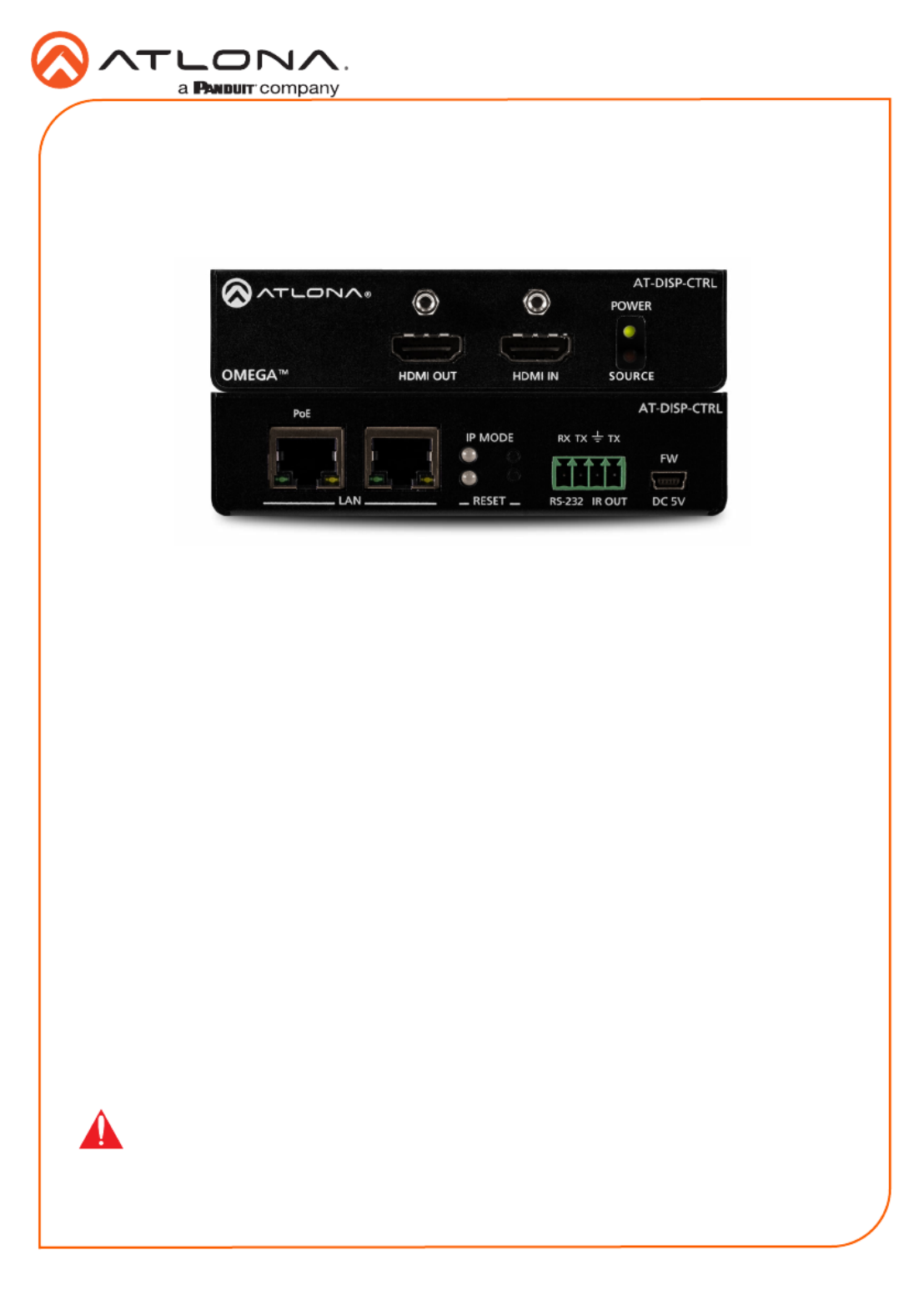
AT-DISP-CTRL
HDMI Display Controller
AT-DISP-CTRL
The Atlona AT-DISP-CTRL is a compact display controller, designed for small meeting spaces
and huddle rooms. The DISP-CTRL detects connection of a source device with an active signal,
and then automatically sends a control command to turn on a display. Similarly, when the device
is disconnected, the DISP-CTRL delivers a command to turn o the display. The DISP-CTRL
can be congured to deliver pre-stored or user-programmed display control commands through
TCP/IP, RS-232, IR, or CEC. Additionally, this controller includes EDID and HDCP management
features, and can be powered locally or through standard Power over Ethernet (PoE). The DISP-
CTRL is HDCP 2.2 compliant and supports 4K/UHD video @ 60 Hz with 4:4:4 chroma sampling,
as well as HDMI data rates up to 18 Gbps.
IMPORTANT: Visit http://www.atlona.com/product/AT-DISP-CTRL for the latest rmware
updates and documentation.
Package Contents
1 x AT-DISP-CTRL
2 x Mounting brackets
4 x Mounting screws
1 x 5 V DC power supply
1 x Installation Guide
Product specificaties
| Merk: | Atlona |
| Categorie: | Controller |
| Model: | AT-DISP-CTRL |
Heb je hulp nodig?
Als je hulp nodig hebt met Atlona AT-DISP-CTRL stel dan hieronder een vraag en andere gebruikers zullen je antwoorden
Handleiding Controller Atlona

12 Juli 2023
12 Juli 2023
12 Juli 2023
Handleiding Controller
Nieuwste handleidingen voor Controller
27 Juli 2026
25 Juli 2026
13 Juli 2026
11 Mei 2026
28 April 2026
15 April 2026
15 April 2026
14 April 2026