AMX MXD-1001-P Handleiding

AMX Monitor MXD-1001-P

Lees hieronder de đź“– handleiding in het Nederlandse voor AMX MXD-1001-P (2 pagina's) in de categorie Monitor. Deze handleiding was nuttig voor 15 personen en werd door 2 gebruikers gemiddeld met 4.5 sterren beoordeeld

Pagina 1/2
Quick Start Guide
MXD-1001 10.1" Modero X Series® G5 Wall/Flush Mount Touch Panel
Overview
In the MXD-1001 10.1” Modero X Series® G5 Wall/Flush Mount Touch Panel, available in
portrait ( ) models, the most elegant interface FG5968-48 FG5968-49) and landscape (
designed specifically for dedicated room control has been significantly enhanced to include a
new G5 Graphic Engine to provide even faster and smoother animations and transitions. It
also quadruples the processing power with a new Quad Core Processor. This new
generation of touch panels is built for usability offering edge-to-edge capacitive touch glass
with multi-touch capabilities. It features advanced technology empowering users to operate
AV equipment seamlessly, while providing the ultimate in audio and video quality. The
distinctive appearance will complement even the most sophisticated meeting facilities and
homes. With a lightning fast processor, brilliant graphics and enhanced capabilities, the
Modero X Series is the control surface that simply delivers more.
For more information on installation and configuration, please refer to the
MXT/MXD-1001 Operation Reference Guide, available at www.amx.com.
Common Applications
The MXD-1001 is ideal for boardrooms, conference rooms or auditoriums where a control
surface is needed to provide access to key functions. In residences, it is perfect for kitchens,
home theaters or home offices where it can be used to manage systems throughout the
house.
Features
•G5 Graphics Engine and Quad Core Processing – The most powerful processing in
the industry delivers smooth gesturing, animations and transitions all at higher speeds
for an experience any user will enjoy.
•Apps - Modero X Series G5 touch panels now have the ability to run stand-alone
applications (apps) within the control environment.
•Simplified Enterprise Touch Panel Updates – Deploy and update touch panel files from
a network URL for simplified company-wide updates.
•Latest Communication Technologies – Supports Near Field Communication™ (NFC) -
short-range wireless technologies that deliver peer-to-peer
communication by 'sharing, pairing and transaction' between RF devices like exchang-
ing data/identities.
•Enhanced Usability – HD video streaming.
•Perfect From Any Angle – Includes In-Plane Switching (IPS), the latest technology in
popular tablet/mobile devices that delivers the widest viewing angles and the most
accurate color reproduction on the market.
Product Specifications
Panel Connectors and Wiring
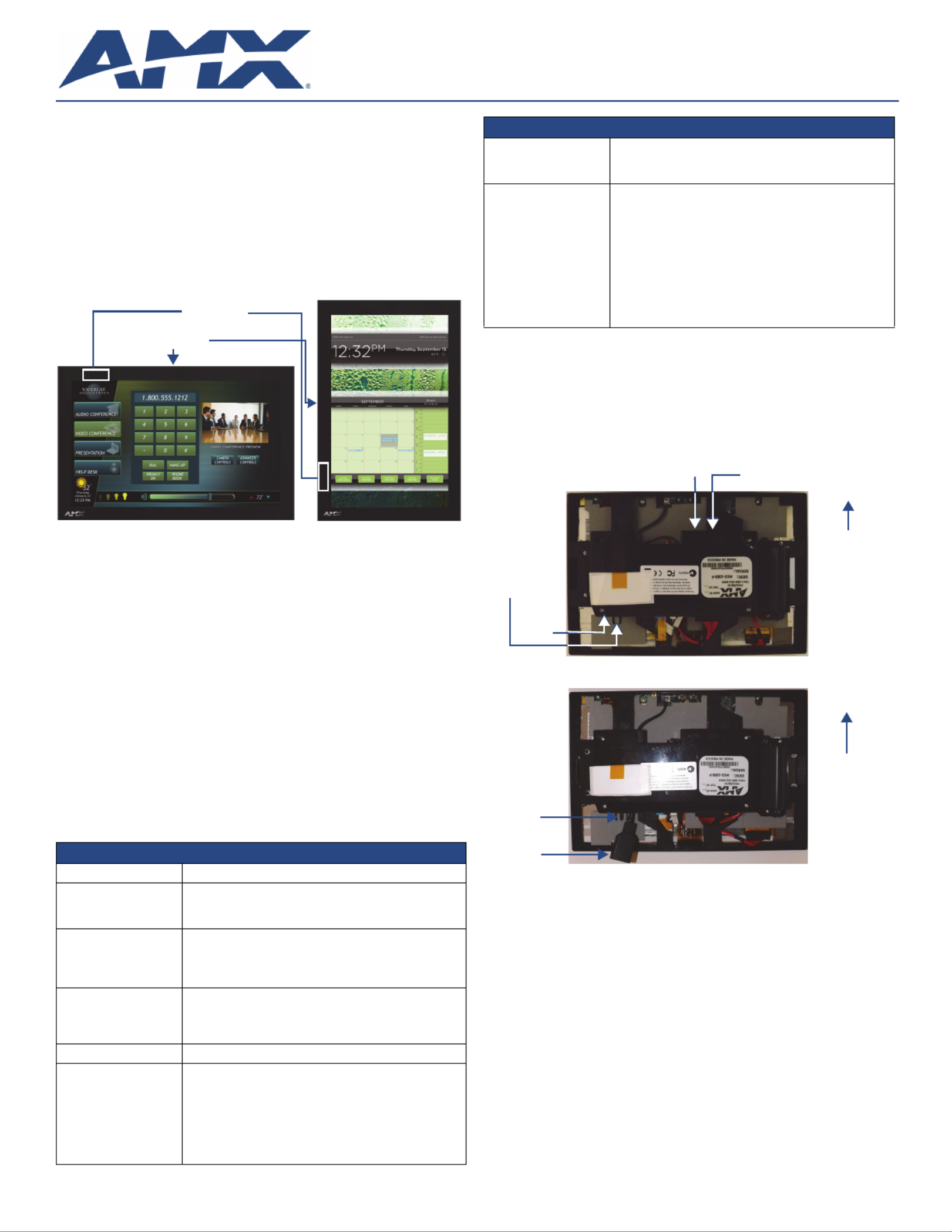
FIG. 2 shows the connectors located on the underside of the MXD-1001. The Micro-USB port
is used for camera video output.
Power for the MXD-1001 via Power Over Ethernet
Power for the MXD-1001 is supplied via Power Over Ethernet (PoE), utilizing an AMX-
certified, capacitive touch-compliant PoE injector such as the PS-POE-AT High Power PoE
Injector (FG423-81) or other approved AMX PoE power source. The incoming Ethernet cable
should be connected to the RJ45 port on the MXD-1001 (FIG. 2 and FIG. 3)
.
Configuring the MXD-1001
The MXD-1001 is equipped with Settings Pages that allow you to set and configure various
features on the panel. For more information on connecting and configuring the
MXD-1001 to a network, please refer to the Modero X Series G5 Programming Guide,
available at www.amx.com.
Accessing the Settings App
To access the Settings app on the MXT-1001, press and hold the Sleep Button (FIG. 1) on
the top of the panel for 3 seconds. The user will be prompted to release the button to enter
the Settings app.
Accessing the NetLinx Subpage
1. From the Settings NetLinx app page, select . This opens a password keypad.
2. Enter the panel password into the keypad (the default is 1988) and select OK to
access the subpage.
Setting the Panel’s Device Number and Device Name
In the NetLinx subpage:
1. Press Device Number to open the NetLinx editing window.
2. Enter a unique Device Number assignment for the panel and press OK.
3. Enter a unique Device Name assignment for the panel and press OK.
FIG. 1 MXD-1001, Landscape and Portrait
MXD-1001 (FG5968-48/49) Specifications
Power: PoE (Power over Ethernet), 802.3af, class 3
Power Consumption: • Full-On: 12.95 W maximum
•Standby: 5.8 W
•Shutdown: 1 W
Operating Environment: • Operating Temperature: 32° F to 104° F (0° C to 40° C)
•Storage Temperature: 4° F to 140° F (-20° C to 60° C)
•Humidity Operating: 20% to 85% RH
•Humidity Storage: 5% to 85% RH
Dimensions (HWD): • Landscape: 6 11/16" x 9 7/8" x 2 5/8" (171 mm x 252 mm x
67 mm)
•Portrait: 9 7/8" x 6 11/16" x 2 5/8" (252 mm x 171 mm x
67 mm)
Weight: 2.0 lbs (0.91 Kg)
Certifications: • UL
• FCC Part 15 Class B
• C-Tick CISPR 22 Class B
• CE EN 55022 Class B and EN 55024
• CB Scheme IEC 60950-1
• IC
• IEC/EN-60950
• RoHS
NFC Sensor
Sleep Button
MXD-1001 (FG5968-48/49) Specifications (Cont.)
Included Accessories: • MXD-1001 Installation Guide (93-5968-48)
• MXA-CLK Modero X Series Cleaning Kit (FG5968-16)
• MXD-1001 Installation Template (68-5968-03)
Other AMX Equipment: • PS-POE-AF-TC, POE Injector, 802.3af Compliant
(FG423-83)
• NXA-ENET8-2POE, Gigabit Switch, 8 Port POE, 2 Port
SFP (FG2178-63)
• MXA-MPL, Modero X Series Multi Preview Live
( )FG5968-10
• MXA-MP, Modero X Series Multi Preview (FG5968-20)
• MXA-RMK-10 10.1” Modero X Series Rack Mount Kit
( )FG5969-62
• MXA-FMK-10, Flush Mount Kit, 10" Modero X Wall
( )FG5968-70
FIG. 2 Rear of the MXD-1001 (Landscape)
FIG. 3 Rear of the MXD-1001 (detail of the RJ45 connection)
RJ45
Port
USB
Port
Micro-USB
Port
Top
RJ45
Cable
Clip
RJ45
Cable
Clip
RJ45
Port
Top
For full warranty information, refer to the AMX Instruction Manual(s) associated with your Product(s).
3/14
©2014 AMX. All rights reserved. AMX and the AMX logo are registered trademarks of AMX.
AMX reserves the right to alter specifications without notice at any time.
3000 RESEARCH DRIVE, RICHARDSON, TX 75082 • 800.222.0193 • fax 469.624.7153 • technical support 800.932.6993 • www.amx.com
93-5968-48 REV: A
Accessing the Ethernet Subpage
1. From the Settings Ethernet app, select . This opens a password keypad.
2. Enter the panel password into the keypad (the default is 1988) and select OK to
access the subpage.
Connecting to a Master
The panel requires that you establish the type of connection you want to make between it
and your Master.
In the NetLinx page:
1. Press Mode to toggle through the available connection modes:
2. If you have enabled password security on your Master, you need to set the username
and password within the device.
a. Select Username to open the NetLinx editing window.
b. Set your Username and Master Password.
e. Click OK to return to the NetLinx page.
Configuring the Panel to a Network
The first step is to configure the panel’s communication parameters. This only configures the
panel to communicate with a network, and it is still necessary to tell the panel with which
Master it should be communicating.
Network Communication With a DHCP Address
In the Ethernet subpage:
1. Toggle the DHCP/Static field to open the DHCP/Static window. DHCP is the default
setting.This action causes all fields on the subpage (other than Ethernet Host Name)
to be greyed-out.
2. Select Host Name to open the Host Name window. Enter the new host name and click
OK.
Network Communication with a Static Address
In the Ethernet subpage:
1. Toggle the DHCP/Static field to open the DHCP/Static window.
2. Select Static in the window. This opens the Static IP editing window.
3. Click on any field to open either a keypad (for numeric entries) or keyboard (for alpha-
numeric entries). To minimize the keypad/keyboard, click the two downward-pointing
arrows at the bottom right corner of the screen.
4. Enter your network’s information in the editing window. To move from field to Static IP
field, simply press the next field you wish to edit.
5. When finished, click OK to save your changes and return to the Ethernet subpage.
Installing the MXD-1001
The MXD-1001 can be installed either directly into a solid surface environment, using either
solid surface screws or the included locking tabs for different mounting options. For more
information, please refer to the MXD-1001 Operation/Reference Guide, available at
www.amx.com.
The MXD-1001 is contained within a clear outer housing known as the back box. This back
box is removed when installing the device into a wall or when using the optional Rough-In
Box accessory ( ). For more information on back box removal, please refer to the FG039-17
MXD/T-1001 Operation Reference Guide, available at www.amx.com.
Installing the MXD-1001 into a wall
The back box (FIG. 4) is designed to attach the panel to most standard wall and solid surface
materials. This back box has four locking tabs (two on top and two on bottom) to help lock the
back box to the wall. These locking tabs are only extended AFTER the back box is inserted
into the wall. Using the locking tabs is highly recommended for standard mounting surfaces
such as walls. For thin walls and solid surfaces, use #4 mounting screws (not included)
.
WARNING: When installing the back box, make sure that the assembly is in the correct
position and in the correct place. Once the locking tabs are extended and locked into place,
removing the back box may be difficult without having access to the back of the wall or
causing damage to the wall.
Note: In order to guarantee a stable installation of the MXD-1001, the thickness of the wall
material must be a minimum of .50 inches (1.27cm) and a maximum of .875 inches (2.22cm).
The surface should also be smooth and flat.
WARNING: The maximum recommended torque to screw in the locking tabs on the plastic
back box is 5 IN-LB [56 N-CM]. Applying excessive torque while tightening the tab screws,
such as with powered screwdrivers, can strip out the locking tabs or damage the plastic back
box.
6. After ensuring proper placement, cut out the mounting surface, using the MXD-1001
Installation Template (68-5968-03) as a guide. Refer to the dimensions in the MXD-
1001 Operation/Reference Guide, available from www.amx.com, for more informa-
tion.
CAUTION: Making sure the actual cutout opening is slightly smaller than the provided
dimensions is highly recommended. This action provides the installer with a margin for error
if the opening needs to be expanded. Too little wall material removed is always better than
too much.
7. Remove the back box knockouts (FIG. 4) and thread the incoming wiring through the
knockout holes.To facilitate installation, thread the Ethernet cable through a bottom
knockout (Landscape) or a right-side knockout (Portrait), and the Micro-USB or USB
cables through a top knockout (Landscape) or left knockout (Portrait).
8. Thread the incoming Ethernet and Micro-USB wiring (if Micro-USB access is desired)
from their terminal locations through the surface opening and through the knockouts.
9. Push the back box flat into the mounting surface and secure with either the locking
tabs or #4 mounting screws (not included). In order to prevent damage to the touch
panel, make sure that any screws used are flush with the back box, and the back box
goes freely into the opening.
10. Insert each connector into its corresponding location along the back of the MXD-1001.
Gently pull the RJ45 adapter from underneath the electronics cover (FIG. 3), attach the
RJ45 cable, and push the connection back under the cover. Lock the RJ45 cable into
the clip above the cable connection (FIG. 2) to facilitate the rest of the installation.
11. Test the incoming wiring by attaching the panel connections to their terminal locations
and applying power. Verify that the panel is receiving power and functioning properly to
prevent repetition of the installation.
NOTE: Do not disconnect the connectors from the touch panel. The unit must be installed
with the attached connectors before being inserted into the drywall.
12. Latch the panel onto the top hooks on the back box and rotate it down (Landscape)
onto the bottom snaps or on the left side and rotate it to the right (Portrait installation)
(FIG. 5). Press gently but firmly on the ends until the snaps “click” to lock it down.
WARNING: if you see a gap between the panel and the back box, or feel any binding while
locking down the panel, stop immediately and verify that no cables or other items are in the
way. Do not force the panel into position, as this can cause damage to the touch screen or
the panel electronics.
13. Reconnect the terminal Ethernet and USB to their respective locations on either the
Ethernet port or NetLinx Master.
Uninstalling the MXD-1001
For information on uninstalling the MXD-1001, please refer to the MXD/T-1001 Operation
Reference Guide, available at www.amx.com.
NOTE: For a demonstration of MXD-1001 uninstallation, please refer to the Modero X Wall
Removal video on the AMXconfigure channel on YouTube:
http://www.youtube.com/user/AMXconfigure/
Connection Modes
Mode Description Procedures
Auto The device connects to the first
master that responds.
This setting requires that you set
the System Number.
Setting the System Number:
1. Select Master System Number to open
the keypad.
2. Set your Master System Number and
select OK.
URL The device connects to the
specific IP of a master via a TCP
connection.
This setting requires that you set
the Master’s IP.
Setting the Master IP:
1. Select the Master IP number to open the
keyboard.
2. Set your Master IP and select OK.
Listen The device “listens” for the
Master to initiate contact.
This setting requires you provide
the master with the device’s IP.
Confirm device IP is on the Master URL list.
You can set the Host Name on the device
and use it to locate the device on the master.
Host Name is particularly useful in the DHCP
scenario where the IP address can change.
FIG. 4 MXD-1001 Back Box Installation (Portrait)
FIG. 5 Installing the MXD-1001
Knockouts
Back Box
Mounting Surface
Locking
Tabs
#4 Screws
Mounting Surface
Back Box
Latch Hooks
Snaps


Product specificaties

Merk: AMX
Categorie: Monitor
Model: MXD-1001-P
Kleur van het product: Zwart
Beeldschermdiagonaal: 10.1 "
Resolutie: 800 x 1280 Pixels
Touchscreen: Ja
Oorspronkelijke beeldverhouding: 9:16
Beeldscherm vorm: Flat
Helderheid: 400 cd/m²
AMD FreeSync: Nee
NVIDIA G-SYNC: Nee
Type processor: Quad Core
Ophangsysteem voor aan de muur: Ja
Touchscreen technologie: Capacitief

Heb je hulp nodig?

Als je hulp nodig hebt met AMX MXD-1001-P stel dan hieronder een vraag en andere gebruikers zullen je antwoorden


Handleiding Monitor AMX

AMX

AMX MXD-1001-P Handleiding

14 November 2023
AMX

AMX NXD-700Vi Handleiding

14 November 2023
AMX

AMX NXD-700i Handleiding

13 November 2023
AMX

AMX MVP-8400i Handleiding

13 November 2023
AMX

AMX MST-431 Handleiding

13 November 2023
AMX

AMX MXT-1000-NC Handleiding

13 November 2023
AMX

AMX NXD-435 Handleiding

13 November 2023
AMX

AMX MXD-701-L Handleiding

13 November 2023

Handleiding Monitor

Nieuwste handleidingen voor Monitor