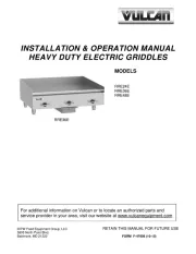
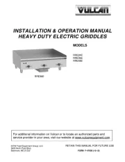
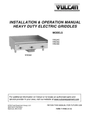
Vulcan HEG72E Handleiding
Vulcan
Grillplaat
HEG72E
Bekijk gratis de handleiding van Vulcan HEG72E (29 pagina’s), behorend tot de categorie Grillplaat. Deze gids werd als nuttig beoordeeld door 32 mensen en kreeg gemiddeld 4.6 sterren uit 16.5 reviews. Heb je een vraag over Vulcan HEG72E of wil je andere gebruikers van dit product iets vragen? Stel een vraag
Pagina 1/29

For additional information on Vulcan-Hart Company or to locate an authorized
parts and service provider in your area, visit our website at www.vulcanequipment.com
VULCAN-HART
DIVISION OF ITW FOOD EQUIPMENT GROUP, LLC
www.vulcanequipment.com
SERVICE MANUAL
This Manual is prepared for the use of trained Vulcan Service
Technicians and should not be used by those not properly
qualifi ed.
This manual is not intended to be all encompassing. If you have
not attended a Vulcan Service School for this product, you should
read, in its entirety, the repair procedure you wish to perform to
determine if you have the necessary tools, instruments and skills
required to perform the procedure. Procedures for which you
do not have the necessary tools, instruments and skills should
be performed by a trained Vulcan Service Technician.
The reproduction, transfer, sale or other use of this Manual,
without the express written consent of Vulcan, is prohibited.
This manual has been provided to you by ITW Food Equipment
Group LLC (“ITW FEG”) without charge and remains the property
of ITW FEG, and by accepting this manual you agree that you will
return it to ITW FEG promptly upon its request for such return
at any time in the future.
BALTIMORE, MD 21222
F45490 (0 )Rev. B 8/21
HEG / WEG Series GriddleRRE /
VULCAN HEG24E
HEG36E
HEG48E
HEG60E
HEG72E
WOLF WEG24E
WEG36E
WEG48E
WEG60E
WEG72E
RRE24E
RRE36E
RRE48E

TABLE OF CONTENTS
SERVICE UPDATES ....................................................................................... 3
SERVICE UPDATES ................................................................................... 3
TIS DOCUMENT LIST - HEG / WEG SERIES ........................................................... 3
GENERAL .................................................................................................. 4
INTRODUCTION . . . . . . . . . . . . . . . . . . . . . . . . . . . . . . . . . . . . . . . . . . . . . . . . . . . . . . . . . . . . . . . . . . . . . . . . . . . . . . . . . . . . . . . 4
MODELS COVERED ................................................................................... 4
INSTALLATION ........................................................................................ 4
CLEANING PROCEDURES . . . . . . . . . . . . . . . . . . . . . . . . . . . . . . . . . . . . . . . . . . . . . . . . . . . . . . . . . . . . . . . . . . . . . . . . . . . . . 4
TOOLS AND TEST EQUIPMENT . . . . . . . . . . . . . . . . . . . . . . . . . . . . . . . . . . . . . . . . . . . . . . . . . . . . . . . . . . . . . . . . . . . . . . . 4
LUBRICATION ......................................................................................... 4
OPERATING CONTROLS . . . . . . . . . . . . . . . . . . . . . . . . . . . . . . . . . . . . . . . . . . . . . . . . . . . . . . . . . . . . . . . . . . . . . . . . . . . . . . 4
THERMOSTAT ..................................................................................... 4
INDICATOR LIGHT . . . . . . . . . . . . . . . . . . . . . . . . . . . . . . . . . . . . . . . . . . . . . . . . . . . . . . . . . . . . . . . . . . . . . . . . . . . . . . . . . 4
REMOVAL AND REPLACEMENT OF PARTS ............................................................... 5
GRIDDLE SERVICE POSITION ......................................................................... 5
HEATING ELEMENT REPLACEMENT . . . . . . . . . . . . . . . . . . . . . . . . . . . . . . . . . . . . . . . . . . . . . . . . . . . . . . . . . . . . . . . . . . 5
THERMOSTAT REPLACEMENT . . . . . . . . . . . . . . . . . . . . . . . . . . . . . . . . . . . . . . . . . . . . . . . . . . . . . . . . . . . . . . . . . . . . . . . . 7
SERVICE PROCEDURES AND ADJUSTMENTS . . . . . . . . . . . . . . . . . . . . . . . . . . . . . . . . . . . . . . . . . . . . . . . . . . . . . . . . . . . . 9
THERMOSTAT CALIBRATION PROCEDURES . . . . . . . . . . . . . . . . . . . . . . . . . . . . . . . . . . . . . . . . . . . . . . . . . . . . . . . . . 9
TESTING VOLTAGE TO HEATER(S) . . . . . . . . . . . . . . . . . . . . . . . . . . . . . . . . . . . . . . . . . . . . . . . . . . . . . . . . . . . . . . . . . . 10
ELECTRICAL OPERATION ................................................................................ 11
PROCEDURE OF OPERATION . . . . . . . . . . . . . . . . . . . . . . . . . . . . . . . . . . . . . . . . . . . . . . . . . . . . . . . . . . . . . . . . . . . . . . . 11
24" WIRING DIAGRAM . . . . . . . . . . . . . . . . . . . . . . . . . . . . . . . . . . . . . . . . . . . . . . . . . . . . . . . . . . . . . . . . . . . . . . . . . . . . . . . . 12
24" SCHEMATIC ...................................................................................... 13
1 & 3 PHASE ...................................................................................... 13
2 PHASE, 3 WIRE . . . . . . . . . . . . . . . . . . . . . . . . . . . . . . . . . . . . . . . . . . . . . . . . . . . . . . . . . . . . . . . . . . . . . . . . . . . . . . . . . 13
36" WIRING DIAGRAM . . . . . . . . . . . . . . . . . . . . . . . . . . . . . . . . . . . . . . . . . . . . . . . . . . . . . . . . . . . . . . . . . . . . . . . . . . . . . . . . 15
36" SCHEMATIC ...................................................................................... 15
1 & 3 PHASE ...................................................................................... 15
2 PHASE, 3 WIRE . . . . . . . . . . . . . . . . . . . . . . . . . . . . . . . . . . . . . . . . . . . . . . . . . . . . . . . . . . . . . . . . . . . . . . . . . . . . . . . . . 16
48" WIRING DIAGRAM . . . . . . . . . . . . . . . . . . . . . . . . . . . . . . . . . . . . . . . . . . . . . . . . . . . . . . . . . . . . . . . . . . . . . . . . . . . . . . . . 18
48" SCHEMATIC ...................................................................................... 18
1 & 3 PHASE ...................................................................................... 18
3 PHASE, 4 WIRE . . . . . . . . . . . . . . . . . . . . . . . . . . . . . . . . . . . . . . . . . . . . . . . . . . . . . . . . . . . . . . . . . . . . . . . . . . . . . . . . . 19
60" WIRING DIAGRAM . . . . . . . . . . . . . . . . . . . . . . . . . . . . . . . . . . . . . . . . . . . . . . . . . . . . . . . . . . . . . . . . . . . . . . . . . . . . . . . . 21
60" SCHEMATIC ...................................................................................... 21
1 & 3 PHASE ...................................................................................... 21
2 PHASE, 3 WIRE . . . . . . . . . . . . . . . . . . . . . . . . . . . . . . . . . . . . . . . . . . . . . . . . . . . . . . . . . . . . . . . . . . . . . . . . . . . . . . . . . 23
72" WIRING DIAGRAM . . . . . . . . . . . . . . . . . . . . . . . . . . . . . . . . . . . . . . . . . . . . . . . . . . . . . . . . . . . . . . . . . . . . . . . . . . . . . . . . 24
72" SCHEMATIC ...................................................................................... 25
1 & 3 PHASE ...................................................................................... 25
2 PHASE, 3 WIRE . . . . . . . . . . . . . . . . . . . . . . . . . . . . . . . . . . . . . . . . . . . . . . . . . . . . . . . . . . . . . . . . . . . . . . . . . . . . . . . . . 26
TROUBLESHOOTING ..................................................................................... 28
TROUBLESHOOTING . . . . . . . . . . . . . . . . . . . . . . . . . . . . . . . . . . . . . . . . . . . . . . . . . . . . . . . . . . . . . . . . . . . . . . . . . . . . . . . . . 28
HEG / WEG / RRE Series Griddle
© HOBART SERVICE 2021
F45490 Rev. B (0821) Page 2 of 29

SERVICE UPDATES
SERVICE UPDATES
August
• Added update to 60" WIRING DIAGRAM.
November, 2018
• Added TIS Document List.
TIS DOCUMENT LIST - HEG / WEG SERIES
SERVICE TAB
Document Title Document Type
HEG-E / WEG-E Heavy Duty Electric Griddles Service
Manual Service Manual
SERVICE TAB (Multimedia)
Document Title Document Type
Repairing Flood-Damaged Food Equipment Misc
HEG-E / WEG-E Heavy Duty Electric Griddles Operation
& Installation Manual Operator
Rating Plate Locations on Current Vulcan-Hart/Wolf
Range Equipment Technical Service Bulletin (TSB)
TSB 1037A Hobart to Vulcan "Common" Model Cross
Reference List Technical Service Bulletin (TSB)
PARTS TAB
Document Title Document Type
HEG-E / WEG-E Heavy Duty Electric Griddles Parts
Catalog Parts Catalog
HEG / WEG / RRE Series Griddle - SERVICE UPDATES
Page 3 of 29 F45490 Rev. B (0821)
Product specificaties
| Merk: | Vulcan |
| Categorie: | Grillplaat |
| Model: | HEG72E |
Heb je hulp nodig?
Als je hulp nodig hebt met Vulcan HEG72E stel dan hieronder een vraag en andere gebruikers zullen je antwoorden
Handleiding Grillplaat Vulcan
9 Juni 2025
9 Juni 2025
9 Juni 2025

9 Juni 2025

6 Januari 2024

6 Januari 2024

5 Januari 2024

5 Januari 2024

15 Augustus 2023

15 Augustus 2023
Handleiding Grillplaat
- Waring Commercial
- Medion
- Korona
- CaterChef
- Bella
- Braun
- Traeger
- Yamazen
- Tepro
- CombiSteel
- Gourmetmaxx
- Listo
- Eldom
- Camry
- Delonghi
Nieuwste handleidingen voor Grillplaat

29 Juli 2025

29 Juli 2025
28 Juli 2025
28 Juli 2025

24 Juli 2025

21 Juli 2025

15 Juli 2025

14 Juli 2025

7 Juli 2025

7 Juli 2025