Viking E-30-PT-EWP Handleiding
Viking Intercomsysteem E-30-PT-EWP
Bekijk gratis de handleiding van Viking E-30-PT-EWP (8 pagina’s), behorend tot de categorie Intercomsysteem. Deze gids werd als nuttig beoordeeld door 17 mensen en kreeg gemiddeld 4.7 sterren uit 5 reviews. Heb je een vraag over Viking E-30-PT-EWP of wil je andere gebruikers van dit product iets vragen? Stel een vraag
Pagina 1/8
PRODUCT MANUAL
Designed, Manufactured and Supported in the USA
SECURITY & COMMUNICATION SOLUTIONS
Provide Reliable and Intelligent
Communication In Noisier Locations
Features
The E-30-PTis designed to provide quick and reliable
communication in noisier areas. The mic sensitivity is set
to a low level until the TALKbutton is pressed then it is
raised to a normal level. In this way, the assuresE-30-PT
that the called party’s voice will be broadcast over the
speaker. In applications where the background noise
can be louder than the person calling, a handset type
phone is recommended.
The E-30-PTfeatures non-volatile memory, a built in
dialer, and intelligent call progress detection for automatic
hang-up when the call is completed. The can beE-30-PT
programmed to dial up to 5 different numbers on ring no
answer or busy and can be configured to dial these
numbers until answered.
The E-30-PT-EWPshares all of the features of the
E-30-PTin addition to Enhanced Weather Protection
(EWP) for outdoor installations where the unit is exposed
to precipitation or condensation. EWP products feature
foam rubber gaskets and boots, silicon sealed
connections, gel-filled butt connectors, as well as
urethane or thermal plastic potted circuit boards with
internally sealed, field-adjustable trim pots and DIP
switches for easy on-site programming.
• Vandal Resistant Features:14 gauge louvered 316
stainless steel faceplate with permanent laser etched
graphics, speaker/mic screen, heavy duty metal “Call”
button and T-10 Torx security mounting screws
• Marine grade 316Weather Resistant Features:
stainless steel faceplate, T-screws and push button
switch. Switch internally sealed per IP67. Mylar
speaker. Self-draining mic mount. Faceplate, mic and
speaker gaskets. Weather resistant powder paint on
optional ().VE-5x5DOD 424
• E-30-PT-EWPis designed to meet IP66 Ingress
Protection Rating (see for more information)DOD 859
• Push to talk button
• Telephone line powered
• Non-volatile E
2
memory (no batteries required)
• Programmable to dial up to 5 numbers on busy or ring
no answer
• Blue off-hook LED indicator
• Volume adjustments for microphone and speaker
• Advanced call progress detection: disconnects on
busy signal, return to dial tone, CPC, reorder tone,
maximum call time out and programmable silence
time out
• Selectable auto-answer feature for monitoring
• Selectable push button disconnect
• Extended temperature range (-30°F to 150°F)
• Flush mountable using included plastic rough-in box
• Optional surface mount back box ()VE-5x5DOD 424
Non-ADA Hot-Line Phones for:
• Terminals• Parking lots/ramps
• Stadiums• Convention centers
• ATM machines
Gate and Door Entry Phones for:
• Business lobbies• Residences
• Vehicular and Pedestrian gates
Power:Telephone line powered. Minimum 24V DC talk
battery voltage, with a minimum loop current of 20mA
loop. Loop current may be boosted on low current lines
with a Viking Model talk battery booster (seeTBB-1B
DOD 632).
Minimum Ring Voltage: 90VAC RMS
Dimensions: Overall-5” x 5” x 2.25” (127mm x 127mm x
57mm), Plastic Electrical Box-4” x 4” x 2.12” (102mm x
102mm x 54mm )
Shipping Weight:2.2 lbs (1 Kg)
Operating Temperature: -30°F to 150°F (-34°C to 65° C)
Humidity - E-30-PT:5% to 95% non-condensing
Humidity - E-30-PT-EWP:Up to 100% condensing
Connections - E-30-PT: RJ11 jack
Connections - E-30-PT-EWP: Gel-filled butt connectors
E-30-PT/EWP
Speaker Phone with
Push to Talk Button
February 5, 2018
Applications
Specifications
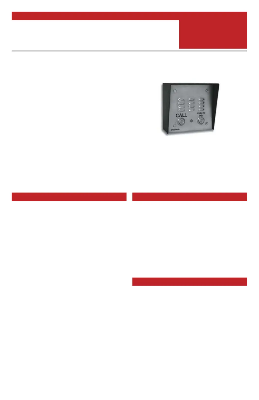
VIKING
E-30-PT/E-30-PT-EWP
Brushed 316 Stainless steel
shown with optional VE-5x5
CAUTION - When installing on an analog extension of a phone
system: Some phone systems do not conform to analog telecom
standards and might not be compatible with the E-30-PT speaker
phones. For a detailed description of the telephone line
specifications required for any of the E-30-PT phones, see DOD#
869.
Product specificaties
| Merk: | Viking |
| Categorie: | Intercomsysteem |
| Model: | E-30-PT-EWP |
| Kleur van het product: | Roestvrijstaal |
| Gewicht: | 1000 g |
| Breedte: | 127 mm |
| Diepte: | 57 mm |
| Hoogte: | 127 mm |
| Internationale veiligheidscode (IP): | IP66 |
| Plaatsing: | Muur |
| Connectiviteitstechnologie: | Bedraad |
| Certificering: | EWP\nIP66\nFCC Part 68\nFCC Part 15 |
| Aantal knoppen: | 2 |
| Binnenunit inbegrepen: | Nee |
| Buitenunit inbegrepen: | Ja |
| Gemakkelijk te installeren: | Ja |
| Outdoor units hoeveelheid: | 1 |
| Bedrijfstemperatuur (T-T): | -26 - 54 °C |
Heb je hulp nodig?
Als je hulp nodig hebt met Viking E-30-PT-EWP stel dan hieronder een vraag en andere gebruikers zullen je antwoorden
Handleiding Intercomsysteem Viking

6 Juni 2025
3 Juni 2025
3 Juni 2025
27 Maart 2025
27 Maart 2025
27 Maart 2025
27 Maart 2025
27 Maart 2025
27 Maart 2025
27 Maart 2025
Handleiding Intercomsysteem
Nieuwste handleidingen voor Intercomsysteem
13 Maart 2026
10 Maart 2026
10 Maart 2026
4 Maart 2026
4 Maart 2026
4 Maart 2026
3 Maart 2026
11 Februari 2026
11 Februari 2026
11 Februari 2026