Valcom V-DCPI Handleiding
Bekijk gratis de handleiding van Valcom V-DCPI (3 pagina’s), behorend tot de categorie Klok. Deze gids werd als nuttig beoordeeld door 34 mensen en kreeg gemiddeld 4.6 sterren uit 7 reviews. Heb je een vraag over Valcom V-DCPI of wil je andere gebruikers van dit product iets vragen? Stel een vraag
Pagina 1/3
Issue 3
1 947972
V-DCPI
Digital Protocol Interface
GENERAL
The Valcom Digital Protocol Interface conditions the
24-hour enhanced digital output from the Valcom
V-SER or V-2927 clock cards to allow the Valcom
communications systems using these cards to
provide clock correction data to a V-WMCA
Wireless Master Clock Transceiver, a V-WMCRA
Wireless Master Clock Repeater, or a V-CCU
2-Wire Clock Controller. The V-CCU is part of the
V-VCU package, which includes the V-CCU and a
power supply.
PACKAGE INCLUDES
1 Valcom V-DCPI Digital Protocol Interface
1 6-Pin Silver-Satin Cord
1 6-Pin RJ-11 Wiring Block
1 DB15 to RJ-45 Gender Changer
1 Ethernet Cable
SPECIFICATIONS
Output
Two individual RJ-11 data outputs
Inputs
RJ-45 for 24-hour enhanced digital from the
Valcom V-SER or V-2927 clock cards
-24VDC input power (for use when providing
data to V-WMCA or V-WMCRA only)
Dry contact closure input to display “Fire” or
“Bell” on wired digital display clocks that are
receiving data once a second.
Features
Data output LED indicator
Easy Connectivity
Dimensions/Weight
2.75”H x 7.70”W x 1.55”D
(6.98cm H x 19.55cm W x 3.94cm D)
1.5 lb. (0.68 kg)
Power Requirements
The V-DCPI requires -24VDC 50mA (1 VPU). The
unit may be powered by a V-CCU connection to the
V-CCU #1 RJ-11 or by connecting a suitable power
supply to the -24VDC input.
Environmental
Operating Temperature: -0 to +40° C
Humidity: 0-95% non-precipitating
Wiring Requirements
24AWG UTP, CAT 3/5/5E/6
Ethernet Cable
6-Pin Silver Satin Cord
6-Pin RJ-11 Wiring Block (for V-WMCA or
V-WMCRA connectivity). When used with a
V-WMCRA, the Wireless Master Clock
Repeater must be set to transmit mode.
INSTALLATION
Precautions
Failure to observe the following precautions could
result in damage to the V-DCPI:
Make all connections to the V-DCPI and
associated equipment with the input power
removed. Check and verify all connections
before applying power.
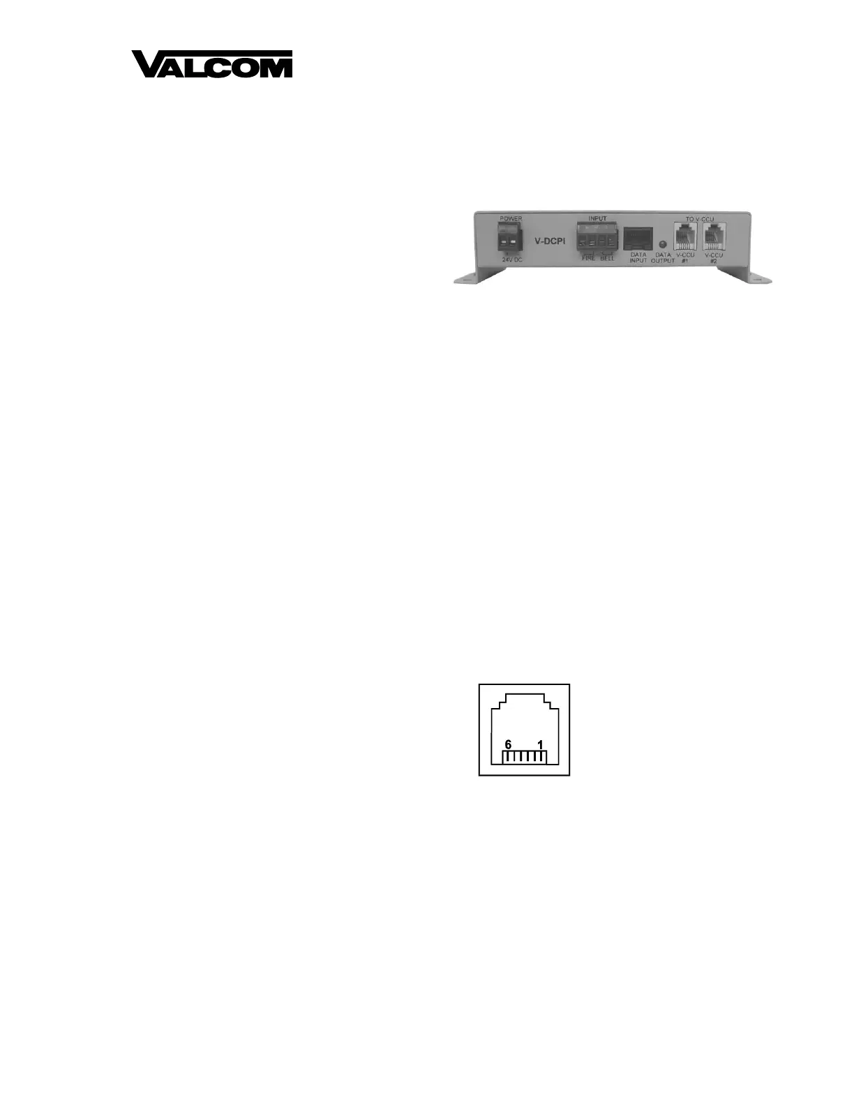
FIGURE 1: V-CCU RJ-11 DETAIL
Data is connected to the V-CCU, V-WMCA or
V-WMCRA via the two center pins of the “DATA
OUT” RJ-11 connector. Electrical shorting of any
RJ-11 pins or terminations may result in unit failure.
The 24V and GND connections are provided as a
power source for the V-DCPI Digital Protocol
Interface when used with a V-CCU 2-Wire Clock
Controller.
OPERATION
The green data output indicator will flicker when
correction data is supplied to the V-CCU outputs.
Pin 1 24V in from V-CCU
Pin 2 GND in from V-CCU
Pin 3 Data
Pin 4 Data
Pin 5 GND in from V-CCU
Pin 6 24V in from V-CCU
Product specificaties
| Merk: | Valcom |
| Categorie: | Klok |
| Model: | V-DCPI |
Heb je hulp nodig?
Als je hulp nodig hebt met Valcom V-DCPI stel dan hieronder een vraag en andere gebruikers zullen je antwoorden
Handleiding Klok Valcom

4 December 2025
29 November 2025
29 November 2025
29 November 2025
27 November 2025
24 November 2025
13 Oktober 2025
23 September 2025
23 September 2025
23 September 2025
Handleiding Klok
Nieuwste handleidingen voor Klok
3 April 2026
2 April 2026
2 April 2026
2 April 2026
1 April 2026
1 April 2026
1 April 2026
31 Maart 2026
16 Maart 2026
16 Maart 2026