Uni-T UT683KIT Handleiding
Uni-T
Meetapparatuur
UT683KIT
Bekijk gratis de handleiding van Uni-T UT683KIT (2 pagina’s), behorend tot de categorie Meetapparatuur. Deze gids werd als nuttig beoordeeld door 36 mensen en kreeg gemiddeld 4.4 sterren uit 18.5 reviews. Heb je een vraag over Uni-T UT683KIT of wil je andere gebruikers van dit product iets vragen? Stel een vraag
Pagina 1/2

1 2
3 4
5 6
7 8
9 10
11 12
13 14
15 16
17 18
19 20
P/N:110401109689X
Preface
Thank you for purchasing this brand new product. In order to use this product
safely and correctly, please read this manual thoroughly, especially the safety
notes.
After reading this manual, it is recommended to keep the manual at an easily
accessible place, preferably close to the device, for future reference.
Limited Warranty and Liability
Uni-Trend guarantees that the product is free from any defect in material and
workmanship within one year from the purchase date. This warranty does
not apply to damage caused by accident, negligence, misuse, modification,
contamination or mishandling. The dealer shall not be entitled to give any
other warranty on behalf of Uni-Trend. If you need warranty service within
the warranty period, please contact your seller directly.
Uni-Trend will not be responsible for any special, indirect, incidental or
subsequent damage or loss caused by using this device.
I. Safety Information
This manual includes precautions and safety regulations for safe use of the
device. Please read and understand the content carefully before use.
1. Do not use or store this device in dusty, hot or wet environments.
2. Both the transmitter and receiver of this device are charged with a DC 5V
power adapter, and the charging time is about 2 hours.
3. Do not use this device on live circuits exceeding AC 60V or DC 70V.
4. Do not use this device during thunderstorms.
The meaning of the symbol associated with this device:
Complies with European Union standards
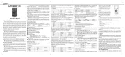
II. Structure
The UT683KIT is an intelligent wire tracker for noiseless wire tracking. The
RJ45 jack of the transmitter can enable tracking and flashing functions
simultaneously to help you quickly and accurately locate the target cable.
The RJ11 jack can automatically identify open circuit, short circuit, polarity,
ringing signal, and other states to help you quickly distinguish cable faults.
It is an ideal tool for integrated wiring and installation and maintenance of
weak electricity systems.
RJ 11 jack
POLARITY indicator
CONT indicator
Switch button
Tracking button
Antenna
Charging state indicator
NCV button
Tracking button
Line sequence indicators
RJ 45 jack
PORT FLASH light
Line sequence indicators
Power button
Validating indicator
NCV indicator
Sensitivity knob
Flashlight button
Power button
RJ45 jack
IV. Network Line Tracking
1. Insert the RJ45 plug of the network line into the RJ45 jack of the transmitter.
2. Press the button on the transmitter to enable the tracking function. In
tracking mode, press the button to enable the flashing function
simultaneously. If the target network line is connected to an active switch,
router or network card, the PORT FLASH light of the transmitter will flash
synchronously with the network port indicator.
3. Press the button on the receiver to start tracking. When beeps are heard,
the target network line is found.
V. Telephone Line Tracking
1. Insert the RJ11 plug of the telephone line into the RJ11 jack of the transmitter.
2. Press the button on the transmitter to enable the tracking function.
4. Press the button on the receiver to start tracking. When beeps are heard,
the target telephone line is found.
VI. Power Cable Tracking
1. Use the RJ11 alligator clip adapter cable to connect the transmitter and
metal cable being tracked.
2. Press the button on the transmitter to enable the tracking function.
3. Press the button on the receiver to start tracking. When beeps are heard,
the target cable is found.
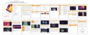
VII. Demonstration of Tracking Operation
III. Packing List
Item Qty Item Qty
Transmitter 1Receiver 1
Micro USB charging cable 1RJ11 adapter cable 1
RJ11 alligator clip adapter cable 1RJ45 adapter cable 1
User manual 1 Pouch 1
Wall socket
(RJ11/RJ45 socket)
Test indicators
Locating cables Isolating cables
Volume control

IX. RJ11 Cable Validating
1. Insert the RJ11 plug of the cable under test into the RJ11 jack of the
transmitter, or use the RJ11 alligator clip adapter cable to connect the
transmitter and metal cable under test.
2. Press the button, the button flashes, and the validating function is
enabled.
3. The CONT indicator lights up green to indicate open circuit of the cable,
and red to indicate short circuit of the cable. The POLARITY indicator lights
up green to indicate that the cable has a positive polarity voltage, red to
indicate that the cable has a reverse polarity voltage, and green and red
flash alternately to indicate a ringing signal or AC power on the cable.
X. Other Functions
1. NCV Function
Press the NCV button to enable the NCV function. When the target cable
or socket has an AC voltage over 40V, the receiver will beep and the NCV
indicator will flash synchronously.
If the target cable are intermixed with massive cables, turn the sensitivity
knob to adjust the sensitivity. Louder sound means stronger signal and closer
to the target cable.
VIII. RJ45 Cable Validating
1. Insert the RJ45 plugs of the cable under test into the RJ45 jacks of the
transmitter and receiver.
2. Press the button, the button flashes, and the validating function is
enabled.
3. Judge the state of the cable (good wiring, short circuit, open circuit, miswire)
according to the line sequence indicators on the transmitter and receiver.
4. During test, press the button to switch between fast and slow mode.
5. The diagram below shows the wiring of different states (good wiring, short
circuit, open circuit, miswire) for unshielded cables.
• Good wiring: LEDs (1~8) on the transmitter and receiver light up in turn.
• Short circuit: No.3 and No.4 LEDs on the receiver light up simultaneously
with dim brightness.
• Open circuit: No.3 LED of the transmitter and receiver do not light up.
• Miswire: LEDs of the transmitter and receiver do not light up correspondingly.
2. Flashlight
Press the button to turn on/off the flashlight of the receiver.
3. Low Battery Indication
1) When the battery voltage 3.4V, the power button will flash.≤
2) When the battery voltage 3.0V, the device will automatically shut
down and need to be charged.
4. Earphones
In noisy environments, users can wear earphones during operation
(earphones need to be prepared by users). Volume can be adjusted by
turning the sensitivity knob.
XI. Specifications
1. Power supply: 3.7V rechargeable batteries
2. Signal mode: modulation signal (125kHz carrier wave)
3. Tracking distance: 3000m (disconnected mode)≥
4. Tracking distance of switch: 100m (connected mode)≥
5. Operating temperature: -10°C~50°C
6. Storage temperature: -20°C~60°C
7. Operating humidity: 20~75% RH (N.C)
8. Storage humidity: 10%~90% RH (N.C)
9. Operating altitude: 2000m≤
10.Dimensions
Transmitter: 130mm×51mm×28mm
Receiver: 197mm×48mm×34mm
11.Weight
Transmitter: about 95g
Receiver: about 127g
12.Applicable standards
EN61326-1:2013 EN61326-2-2:2013
EN61000-3-2:2014 EN61000-3-3:2013
XII. Maintenance and Repair
1. Maintenance
Clean the casing with a dry cloth. Do not use abrasives or solvents!
2. Repair
Please contact your seller directly if the following anomalies occur.
1) Damage of casing or parts
2) Abnormal LED indication
3) Button failure
≤
UT683T Transmitter Lamp Signal UT683R Receiver Lamp Signal
1-8
Good
wiring
3,4
Short
circuit
3
Open
circuit
3,4
Miswire
Product specificaties
| Merk: | Uni-T |
| Categorie: | Meetapparatuur |
| Model: | UT683KIT |
Heb je hulp nodig?
Als je hulp nodig hebt met Uni-T UT683KIT stel dan hieronder een vraag en andere gebruikers zullen je antwoorden
Handleiding Meetapparatuur Uni-T

9 Juni 2025
1 Mei 2025

12 April 2025
5 April 2025

3 April 2025

3 April 2025

3 April 2025

3 April 2025

3 April 2025

3 April 2025
Handleiding Meetapparatuur
- Enda
- Tempo
- AREXX
- DriveTest
- Mitsubishi
- Shimano
- Technics
- P3 International
- Eurolite
- Amprobe
- Owon
- Fysic
- Smart365
- SRS
- IFM
Nieuwste handleidingen voor Meetapparatuur
29 Juli 2025
29 Juli 2025

29 Juli 2025
29 Juli 2025
29 Juli 2025
29 Juli 2025

28 Juli 2025

28 Juli 2025
28 Juli 2025

28 Juli 2025