Uni-T UT512 Handleiding
Uni-T
Meetapparatuur
UT512
Bekijk gratis de handleiding van Uni-T UT512 (2 pagina’s), behorend tot de categorie Meetapparatuur. Deze gids werd als nuttig beoordeeld door 26 mensen en kreeg gemiddeld 4.4 sterren uit 13.5 reviews. Heb je een vraag over Uni-T UT512 of wil je andere gebruikers van dit product iets vragen? Stel een vraag
Pagina 1/2

Introduction
Uni- rend Model UT512 insulation resistance testeT r
(hereafte "the Meter") is handheld instrumenr, a t
designed primarily make resis ance insula io to t / t n
resistance measurement.
Unpacking the Meter
The Meter includes the following items:
Table 1. Unpacking Inspection
Item
1
2
3
4
5
6
7
8
9
Description
English Operating Manual
One-plug t t es lead to one alligator
clip ( Black )
O ne plug es t t lead to one alligator
clip ( Green )
Two-plug test lead to one
alligator clip ( Red )
1.5V Battery (LR14 / R14)
Tool Box
USB Interface Cable
Software
Power adaptor (input voltage
230V, 50/60Hz, 50mA, output
DC14.5V, 600mA) (optional,
available at extra cost)
Qty
1 pc
1 pc
1 pc
1 pc
8 pcs
1 pc
1 pc
1 pc
1 pc
In the event you find any missing or damage, pleas e
contact your dealer immediately.
Safety Information
T his Me er compliest with EN 61010-1:2010 fety sa measurement
requirement:Pollution Degree 2, measurement
category CAT III 600V and Double Insulation.
CAT II (measurement category): Test and measuring
circuits connected directly to utilization points (socket outlets
and similar points) of the low-voltage MAINS installation.
Use the Meter only as specified in this operating manual,
otherwise the protection provided by the Meter may be
impaired.
Danger identifies conditions and actions that pos e
hazard(s) to the user.
Warning alerts users to avoid electric shock.
Caution identifies conditions and actions that ma y
damage the Meter and affect accurate
measurement.
Danger
Use of instrument in a manual not specifed by th e
manufactuer may impair safety features/protection
prov ed by the e nt. d the f gid quipme Rea ollowin
sa rma care refety info tion full foy be us oring
servicing the instrument.
Do not apply more than 600V.
Do not use the Meter around explosive gas,
vapor or dust.
Do not use the Meter in a wet environment.
When using the test leads, keep your figure s
away from the lead contacts. Keep your
figures behind the finger guards on the leads .
Do t u the th any p or co rno se Meter wi arts ve
removed.
Operating Caution identifies conditions that user
needs to t ake ex rat care during opera ting the Meter
Warning
Do not use the Meter if it is damaged or metal
part is exposed. Look for cracks or missing
plastic.
Be careful when working above 33V rms, 46.7 V
ac rms or 70V DC. Such voltages pose a shock
hazard.
Discharge all loading of circuit under test afte r
measuring high voltage.
When carrying out insulation measurement,
do not contact the circuit under test.
Caution
When performing resistance tests, remove all
power from the circuit to be measured and
discharge all the power.
Wh ing then icserv e Meter, u y se onl only the
test leads and power adaptor with the same
model number or identical electrical
specifications.
Do not use the Meter if the battery indicator
( ) a shows battery empty condition. Take
the battery out from the Meter if it is not use d
for a long time.
Do not use or store the Meter in an
environment of high temperature, humidity,
explosive, inflammable and strong magnetic
field. The performance of the Meter may
deteriorate after dampened.
So c th a m dft lo nd ild etergent s be u dhould se
to clean the surface of the Meter when
servicing. No abrasive and solvent should be
u d to p nt the su of the omse reve rface Meter fr
corrosion, damage and accident.
Dry the Meter before storing if it is wet.
Risk of electric shock
Grounding
Empty of Built-In Battery
Con ormsf to St of andards European Union
International Electrical Symbols
International symbols on the Meter and in this manual
are explained in Table 2.
Table 2. International Electrical Symbols
Battery Saver (Sleep Mode)
The Meter enters the Sleep Mode and blanks the displa y
if there is no button press for 15 minutes. This is don e
to conserve battery powe The Meter comes out r. of
Sleep Mode whe button is pressed and hol n ON/OFF d
for 1 second.
Battery Indication
There is a battery indicator shown on the upper left corner
of the display. Please refer to Table 3 for detailed
explanation.
Battery Voltage
5.9V ~ 10.6V. It means the battery is
empty, Do not use the Meter as it
cannot
guarantee accuracy.
10.7V ~ 11.1V. It means the battery is
almost empty, replacing battery is
necessary. At this status, the Meter can
still output 500V and 1000V to measure,
the measured accuracy will not be
affected.
11.2V ~ 12.2V
12.2V or more
Table 3. Battery Indication
Battery
Indicator
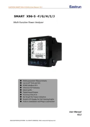
The Meter Structure
Below Figure and 1 Table shows the Meter fron 4 t
structure and description
Do not change battery when the Meter is in
wet environment.
Place test leads in proper input terminals.
Make sure all the test leads are firmly
connected to the Meter's input terminals.
Make sure the Meter is turned off when
opening the battery compartment.
Figure 1. The Meter Front Structur e
G n kree Blac Red
1
2
3
4
5
6
7
8
9
10
11
12
13
14
15
16
Table 4. Meter Front Description
LCD
Arrow Button
Emergency Stop
Data Clear the Display Backlight Button
Arrow Button
On/Off Button
Compare Button
Insulation Resistance Button
DC ButtonVoltage Measurement
Timer Button.
AC ButtonVoltage Measurement
Test Button
USB Button
Data Store Button.
Data Recall Button
Arrow Button
17
18
19
20
21
22
Arrow Button
LINE: High voltage input terminal
( Connected to two-plug red test lead )
High voltage line shielding input terminal
( Connected to two-plug red test lead )
GUARD: Grounding protection input terminal
( Connected to one-plug black test lead )
EA TH:R High resistance measurement input
terminal ( Connected to one-plug green
test lead )
Testing leads:
Two-plug te red st lead one alliga to tor lip c .
One-plug k tblac es leadt to one alliga ort clip.
One-plug green test lead to one alligator clip.
Below Figure 2 and Table 5 shows the Meter side
structure and description
Figure 2. The Meter Side Structure
Table ide De ip io 5. Meter S scr t n
1 Safety Shutter
2 Power adaptor Input Terminal
3 USB Port
Display
Table 6 and Figure 3 describe the display.
Figure 3. Display
Table 6. Display Description
Number
1
2
3
4
5
6
7
8
9
10
11
Meaning
Analogue bar graph
Risk of electric shock
Battery life indicator
Indicator for timer
Timer 1 symbol
Timer 2 symbo
Indicates selected pass/fail compare value
Indicator for power adaptor
The continuity buzzer is on
Indicator for data store full
Data store is on
12
13
14
15
16
17
18
19
20
21
Data recall is on
Indicator for polarization index
Step symbol
Compare result: Pass
Compare result: Fail
Indicator for DC voltage
Indicator for AC voltage
Indicates negative reading
Unit symbols
Indicator for clearing
Table 7. Key Description
Turn on or off the Meter. Press and
hold he t bu on ortt f 1 to t thesecond urn
Meter on. Press again to turn off the
Meter.
The Meter defaults at 500V range and
under continuous measurement of
insulation resistance when turned on.
Emergency stop button. Press this
button when the Meter crashes down
and cannot turn off the power.
Key Functions
ON/OFF
E-STOP
Short press to turn on or off the display
backlight
Long press to clear the stored data.
Press to store the current measurement
value. The maximum number of stored
reading is 18. When the stored readings
memory is full, the Meter shows FULL
and stop storing. Press and hold
CLEAR / to clear the stored value
in order to st t t tore he nex measuremen
CLEAR
/
SAVE
value.
LOAD Press once to recall the first stored
value.
Press again to exit Load feature.
Load feature can only be used when
there is no high voltage output.
When the insulation resistance
measurement has no testing voltage
output, press to select previous voltage
range.
Under load mode: press to recall the
previous stored value.
When the insulation resistance
measurement has no testing voltage
output, press to select next voltage
range.
Under load mode: press to recall the
next stored value.
When setting the timer for the
measurement of insulation resistanc e
or polarization index, press to
decrement the time. The maximu m
length of time is 15 minutes and 30
seconds, the Meter will automaticall y
carry out measurement.
When compare function is enabled for
insulation resistance measurement,
press to decrement a resistance
comparing value.
After polarization index measurement,
press to display polarization index,
TIME 2 and TIME 1 insulation
resistance values in sequence.
When setting the timer for the
measurement of insulation resistanc e
or polarization index, press to
increment the time. The maximum
length of time is 30 minutes and 30
sec tonds, he Meter will automatic yall
carry out measurement.
When compare function is enabled for
insulation resistance measurement,
press to increment a resistance
comparing value.
After polarization index measurement,
press to display t polariza ion index,
TIME 2 and TIME 1 insulation
resistance values in sequence.
Press once to start the data
transferring to the computer via USB ,
USB symbol shows on the display.
Press again to stop the data
transferring to the computer via USB ,
USB symbol disappears.
USB
Set a pass / fail limit for insulation tests.
The default value is 10M
Press to step through continuous,
timed and polarization index
measurements in sequence.
Press to turn on/off the output of
insulation resistance test voltage.
Press to initiate insulation resistance
measurement
Press to initiate DC voltage
measurement
Pres to initiate AC voltage
measurement
COMP
TIME
TEST
IR
DCV
ACV
Measurement Operation
This section explains how to make measurements.
Press and hold to turn on the Meter, pressON/OFF
again to turn off the Mete r. The meter defaults at 500V
range and continuous measurement of insulation
resistance when turned on.
A. Measuring Voltage
Figure 4. Voltage Measurement
Red
Green
To avoid harm to you or damage to the Meter,
please do not attempt to measure voltages
higher than 600V or 600V rms, although
readings may be obtained.
Special care should be taken when measurin g
high voltage.
Operating Caution
To m sure v t , set t Meter as F re 4 ea ol age up he igu and
do the following:
Press or button to select DC voltage orDCV ACV
AC voltage measurement
1.
CAT III (measurement category): Test and measuring
circuits connected to the distribution part of the building’s
low-voltage MAINS installation.
Equipment protected throughout by DOUBLE
INSULATION or REINFORECD INSULATION
Direct current
Alternating current
Caution

This operating manual is subject to change without notice.
*END*
Insert the red and green test leads into and EARTH
two terminals.LINE
When measuring DC voltage, if negative voltage is
present on the red test lead, "-" symbol will show on
the display.
2.
3.
When voltage measurement has been completed,
disconnect the connection between the testing
leads and the circuit under test and remove testing
leads away from the input terminals of the Meter.
Note
Black
Red
B. Measuring Insulation Resistance
Figure 5. Insulation Resistance Measurement
Green
Groud
Operating Cautio n
When performing insulation resistance tests,
remove all power from the circuit to be
measured and discharge all the power.
Operating the Meter must be very careful as it
outputs dangerous voltage during
measurement. Must make sure the tested object
is firmed clipped, hands are away from the
clips, then press TEST button to output high
voltage.
Do not short circuit the testing leads during
high voltages output or test insulation
resistance after high voltages output. This kind
of in correc erat op ting may ca se u sp andarking
fire, which damages the Meter and cause
personal injury.
Do not measure over 10 seconds when:
measuring resistance <2MΩ with use of 500V.
measuring resistance <5MΩ with use of 1000V.
measuring resistance <8MΩ with use of 1500V.
measuring resistance <10MΩ with use of 2500V.
To measure insulation resistance, set up the Meter as
Figure 5 and do the following:
Press button to select insulation resistanceIR
measurement.
When there is no testing voltage output, press
and button to select 500V, 1000V, 2500V
or 5000V voltage range.
W hen pe ingrf rmo in ulas tion resistance tests, remove
all power from the circuit to be measured and
discharge all the power.
Insert the red test lead into two terminals, the LINE
black one into and the green one into GUARD EARTH.
Connect the red and green alligator clip to the circui t
to be measured, negative voltage outputs from LINE
terminal.
Choose one of insulation resistance measurement
modes shown as below:
1.
2.
3.
4.
5.
6.
Press button to select continuousTIME
m , t r s timer c the LCD.ode he e i no i on on
Press and hold button for 1 second toTEST
begin and output insulation resistance test voltage,
TEST button lights up,
blinks on every 0.5
Press TEST button to turn off the voltage output,
when measurement is t .comple ed T TES
ts ofbu ontt ligh f, . The LCD shows disappears
the current insulation resistance measurement
value.
Press button to select timed mode, theTIME
LCD displays and symbols.TIME 1
Press and buttons to set the time (00:10~15:00).
Wit 1 m te, t time em t or em thin inu he incr en decr en
by every 5 seconds. Afterward, the time incremen t
or decrement by every 30 seconds.
T pre hen ss and hold TEST button for 2 sec toond
carry out timed measurement. TIME 1 and are
displayed and blinked on the LCD on every 0.5
seconds.
When the set time is reached, the test voltage
output will be turned off, and the measurement will
be automatically stopped. L di l The CD sp ays the
i lnsu at oni res stance readi ing.
Press button to select timed mode, the LCDTIME
displays and TIME 1 symbols.
Press and buttons to set the time (00:10~15:00).
Within 1 minute, the time increment or decrement
by every 5 seconds. Afterward, the time increment
or decrement by every 30 seconds.
Press TIME bu ontt again. TIME 2, PI and symbols
appear on the LCD.
Press and buttons to set the time (00:15~15:30).
Within 1 minute, the time increment or decrement
by every 10 seconds. After ard,w the time increment
or decrement by every 30 seconds.
Then press and hold TEST button for 2 toseconds
carry out the measurement.
TIME 1 and are displayed and blinked on the
LCD on every 0.5 seconds before set timeTIME 1
is reached.
TIME 2 and are displayed and blinked on the
LCD on every 0.5 seconds before set timeTIME 2
is reached.
When the two set time are reached, the test voltage
output will be turned off and the measurement will
be automatically stopped. The LCD displays the
polarization index reading.
Press to step through the polarization index,
TIME 2 TIME 2 and insulation resistance readings.
Calculation Tips:
PI = 3-minute ~ 10-minute resistance/30-second ~
1-minute resistance
PI
Standard
4 or more
The best
4~2
Good
2.0~1.0
Warning
1.0 or less
Bad
Press button to select compare feature.COMP
COMP symbol displays on the LCD.
Press and buttons to set the compare value
You can choose the compare value from
10M , 20M , 30M , 40M , 50M , 60MΩΩΩΩΩΩ,
70M , 80M , 90M , 100M , 200M , 300MΩ Ω Ω Ω Ω Ω,
400M , Ω500M , Ω600M , Ω700M , Ω800M , Ω900MΩ
1G , 2G , 3G , 4G , 5G , 6G , 7G , 8GΩΩΩΩΩΩΩΩ,
9G , G , Ω10 Ω20 330G , ΩG , G , G , GΩ40 Ω50 Ω60 Ω,
70G , 80G , 90G , 100GΩ Ω Ω Ω
Press and hold TEST button for 2 seconds to carr y
out the measurement.
The symbol will display if the insulationNG
resistance value is smaller than compare value.
Otherwise symbol will be displayed. GOOD
Using Power Adaptor
Refer to Figure 6 for the use of power adaptor.
Figure 6. Using Power Adaptor
Open the side safey shutte r, then you will see ther e
is a power adaptor input terminal.
Make sure the Meter is power off and Insert the
UT512 power adaptor to the input terminal.
It is highly recommended to take out all the batteries
when you are using the power adaptor.
Make sure the Meter is power off when you
disconnect the UT512 power adaptor from the Meter.
It is highly recommended to use Uni-Trend supplied
UT512 power adaptor to avoid unnecessary danger.
1.
2.
3.
4.
5.
Connecting USB Interface
See Figure 7 for USB interface connection.
Figure 7. USB Interface Connection
Install the included software, the installation guide
can be seen from the CD.
Open the side safety shutter, then you will see there
is a USB port.
Insert the included USB cable to the Meter's USB
port and the other end to the computer.
1.
2.
3.
Maintenance
This section provides basic maintenance information
including battery replacement instruction.
Warning
Do not att ptem to pair or re service y r Metou er unless
you are qualified to do so and have the relevant
calibration, performance test, and service
information.
Turn the Meter to OFF when it is not in use.
Take out the battery when it is not using for a long
time.
Do no t use or ore t Meter a st he in place of hu idim ty,
high temperature, exp osl ive, inf ammabl le and stron g
magnetic field.
If the Meter is wet, dry it before use.
B. Replacing the Battery
Warning
To avoid electric shock, remove all the test leads
from the Meter when replacing the batteries.
Figure 8. Battery Replacement
Operating Caution
Do not mix to use old and new batteries.
Be careful the polarity is correct when installin g
batteries.
Do not use the Meter if the battery indicator
( ) shows.
Do you carry out measurement during the
battery compartment is open.
Follow Figure 8 and proceed as follows to replace the
battery:
Turn the Meter to OFF and remove all connection s
from the terminals.
Remove the screw from the battery compartment,
and separate the battery compartment from the case
bottom.
Replace with 8pcs of new 1.5V (LR14) batteries.
Rejoin the case bottom and battery compartment,
and reinstall the screw.
Specifications
Safety and Compliances
Certification
Compliances IEC 61010 CAT.III 600V overvoltage and double insulation standard
General Specifications
Display (LCD)
Operating Temperature
Storage Temperature
Relative Humidity
Battery Type
Dimensions (HxW xL)
Weight
Digital: 9999 counts Analog bar graph.
-10 ~40 (14 ~104 )
-20 ~60 (-4 ~152 )
85% @ -10 ~40 below;
90% @ -20 ~60 :
8pcs of 1.5V (LR14) batteries or power adaptor (input voltage 230 V, ,50/60Hz
50mA, input DC14.5V, 600mA).
Power adaptor is optional at extra cost.
202 x 155 x 94 mm
Approx 2kg (including battery)
Overloading
Battery Indicator
Icon Display
Current Consumption
Display on insulation resistance rangeOL
Display
Equips with function and battery indicator icons .
Maximum: around 600mA
Average: around 20mA
Display Backlight
Computer connection
Data Logging and Recall
Autorange
Warning
Test Voltage
COMP Measurement
PI Measurement
TIME
Bright backlight for clear readings in poorly lighted areas.
Via USB interface.
18
The Meter automatically selects best range
and red light will on.
Automatically source the voltage.
Use the Compare function to set a pass/fail compare level for the insulation
measurements.
Polarization Index is the ratio of insulation resistance. Preset the timer for two
points and the Meter will carry out the measurement automatically.
To carry out measurement by setting a specified time within 15 minutes.
Measurement Range
Resolution
Accuracy
DC Voltage
30 ~ 600V
Accuracy Specifications
Accuracy: ([% of reading] [number of least significant digits), guarantee for yea + 1 r.
Operating temperature: 18 ~28
Relative humidity: 45~75%RH
A. Voltage Measurement
AC Voltage
30V~600V (50/60Hz)
1V
(2%+5) <100V: (2%+8)
100V: (2%+5)
Output Voltage
Display Range
Open Circuit Voltage
Test Current
Short Circuit
Accuracy
B. Insulation Resistance Measurement
500V
0.5M ~5.0GΩ Ω
DC 500V + 20%, -0%
1mA~1.2mA @500k Ω
1000V
2M ~10.0G
DC1000V + 20%, -0%
1mA~1.2mA @ 1M
1500V
5M ~20.0G
DC 2500V + 20%, -0%
1mA~1.2mA @ 1.5M
2500V
10M ~100G
DC2500V + 20%, -0%
1mA~1.2mA @ 2.5M
Less than 2.0mA
100k ~ 100M (3%+5):
100M ~ 10G (5%+5):
10G ~ 100G (10%+5):
At any output voltage, when the tested resistance is less than 10M , the testing time cannot exceed 10
seconds continuously.
Operating Caution
A. General Service
Periodically wipe the case with a damp cloth and
mild detergent. Do not use abrasives or solvents.
To c tlean he terminals with cotton bar with deter t,gen
as dirt or moisture in the terminals can affect
readings.
seconds.
P/N:110401105604X DATE:2018.06.26 REV.7
Product specificaties
| Merk: | Uni-T |
| Categorie: | Meetapparatuur |
| Model: | UT512 |
Heb je hulp nodig?
Als je hulp nodig hebt met Uni-T UT512 stel dan hieronder een vraag en andere gebruikers zullen je antwoorden
Handleiding Meetapparatuur Uni-T

9 Juni 2025
1 Mei 2025

12 April 2025
5 April 2025

3 April 2025

3 April 2025

3 April 2025

3 April 2025

3 April 2025

3 April 2025
Handleiding Meetapparatuur
- Powerfix
- Goobay
- Milesight
- Grohe
- Senseca
- Grundfos
- CESYS
- Technics
- Trumeter
- Kopp
- Siglent
- Holzmann
- Rotronic
- Weidmüller
- J.P. Instruments
Nieuwste handleidingen voor Meetapparatuur
29 Juli 2025
29 Juli 2025
29 Juli 2025
29 Juli 2025
29 Juli 2025
29 Juli 2025
28 Juli 2025
28 Juli 2025
28 Juli 2025
28 Juli 2025