Uni-T UT25B Handleiding
Uni-T Famegmunkálás UT25B
Bekijk gratis de handleiding van Uni-T UT25B (1 pagina’s), behorend tot de categorie Famegmunkálás. Deze gids werd als nuttig beoordeeld door 139 mensen en kreeg gemiddeld 4.4 sterren uit 7 reviews. Heb je een vraag over Uni-T UT25B of wil je andere gebruikers van dit product iets vragen? Stel een vraag
Pagina 1/1
UT25
A,
UT25B
,
UT25B
Operati
o
n
s
Manual
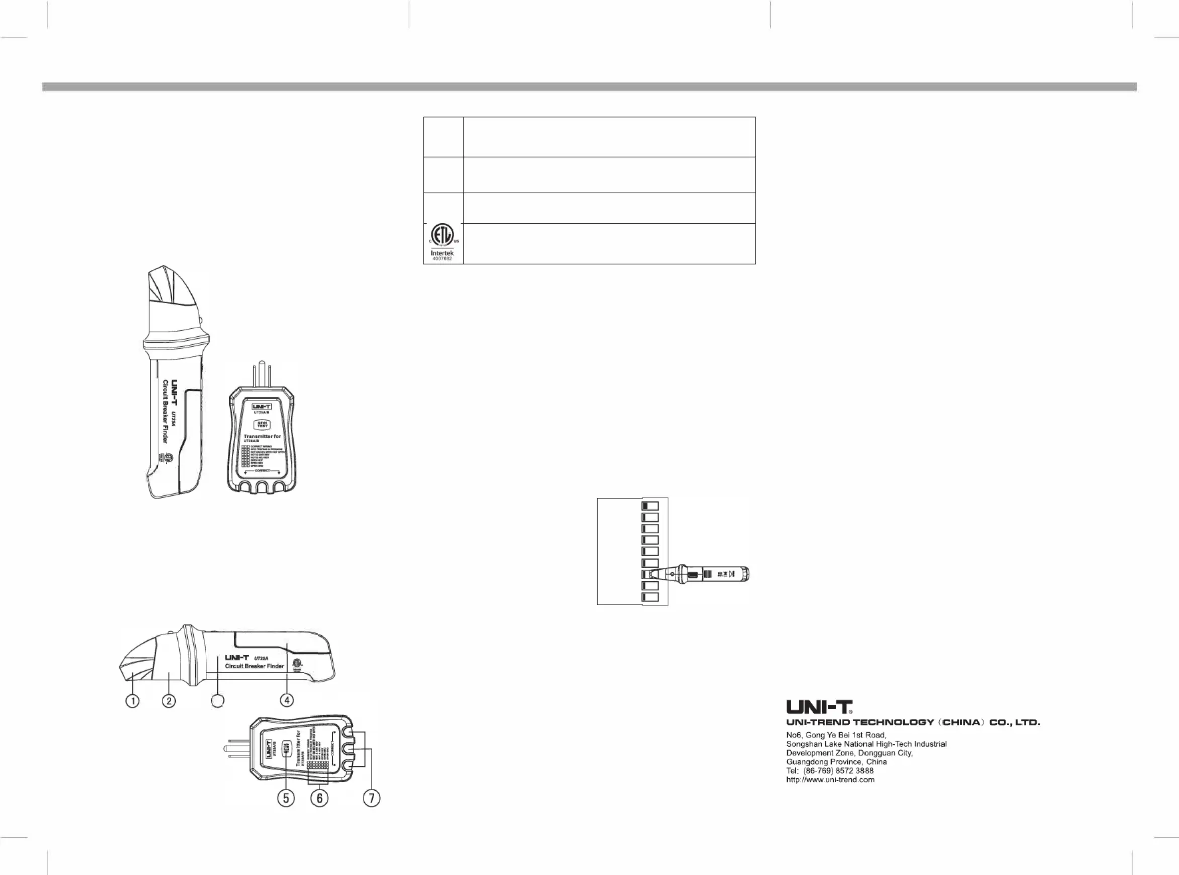
Overall Appearances of Circuit Breaker Finder &
GFCI Socket Tester:
Product Description
Receiver
NCV indicator light (only for UT25B)
LED indicator light with line-tracking
ON/OFF that switch can also adjust sensitivity
9VDC, battery type 1604/6F22
Attention: The battery information on the battery compartment and the
method of opening the battery compartment
Transmitter
�
When the this symbol appears, the operator should refer to
Operations Manual to avoid personal injury or damaging the
meter.
WARNING
When this symbol appears, it hints that there could be potential
danger which might lead to severe injury or death or if the danger is
not avoided.
CAUTION
When this symbol appears, it hints danger that there is potential
which might damage the product if the danger is not avoided.
Conforms to UL STD. 61010-1, Certified to CSA STD C22.2 NO.
61010-1
Product Specification for UT25Aand UT25B
NCV working voltage----------------- 80V(only for UT25B)
Operating voltage--------------------- 90-120V
Operating frequency----------------- 50-60Hz
Operating temperature------- 41'F - 104 'F (5'C - 40'C) -------
Storage temperature---------4'F - 140'F (-20'C - 60'C) --------
Operating humidity------------- at most 80% at temperature of 87'F (31 'C) to ------
50% at temperature of 104'F (40 'C) Storage
humidity------------------------ ---------<80%
Operating altitude---------- ----------7000 feet (2000m) at most
Product weight----------- 133-------------g (UT25A, UT25B)
80g (UT25A/B)
Product size---------------L:192xW:54xH:28mm (UT25A, UT25B) ------------
L:103
xW:
56xH:30mm (UT25A/B)
Product certification------------ ------ETL
ETL list--------------------------- -------ETL mark does not indicate accuracy the of
estimated readings
Operations
Warning: Make sure that the circuit
is functioning properly before using.
Warning: Make sure the user
understands about the equipment.
Find the or location of circuit breaker
circuit protector on the power frequency
circuit loop, the transmitter will then
send out a signal which will be received
by the receiver. The receiver will detect
this signal which is makingbeeping
sounds, the exact position of circuit
breaker circuit or protector can be found
by sensitivity. adjusting the
D
D
(
Detection Receiver) Image of
1.
Plug the receiver into a live socket; two green LEDs will shine.
2.
Unscrew the sensitivity adjusting knob on the receiver from the close to position
the highest position, the red LED will be turned on. If the LED did turn on, red not
please battery change the battery. It is also necessary to change the if the NCV
indicator light and line-tracking light blinking (only for UT25B). are both
3.
During the testing process, when the receiver is to close the transmitter, the
receiver will make beeping sounds and the LED will blink. UT25B (only) will
firstly determine if there is electricity or not. If there is an AC voltage higher
than sounds80V, the NCV indicator light will blink and make beeping . When it
detects signal sent out by the transmitter, it will automatically test the
line-tracking function.
4.
On the circuit breaker panel, adjust the sensitivity to the highest position, hold
the receiver and detect from top to bottom, as shown in the figure above.
5.
Along with the surface of circuit breaker, move the receiver until it detects the
portion of interest.
UNI-
6. When moving the the receiver, sensitivity can be reduced to find
the exact circuit breaker of interest.
•o•
•••
o••
000
ooe
OOFF • ON
Plug the transmitter into the socket.
The operator can determine the status of circuit connection according to the 3
LEDs. shows aThe picture above ll of the circumstances that can appear on
the detected circuit. The picture is observed from the side of GFCI buttons. If
it is observed from the other side, the order of LED indicator lights will be
mirrored.
This equipment cannot detect the hot ground connection if there are 2
wires, a combination circuit, or the ground and neutral wires are reversed.
GFCI Test on Socket:
Before using thisGFCI equipment, press button to check if it can returnto
theoriginalposition.the If not, please donot plug equipment into electrical
circuit,engineerforhelp. and ask for a professional electrical If the button
works, please press the button on the socket.
Plugthe transmitter into socket and check if the circuit is connected correctly.
Press GFCI button for at least 8 seconds,light the indicator will be turned
off when the GFCI button is released.
lf the circuit didnot resetthe GFCI button, it could be that the GFCI button is
correct, but the wire connection isnot .Oritcouldbeconnection that the wire
is correct, butthe GFCI button is not.
Changing Battery:
When the battery voltage is lower than the working voltage, the indicator
lights on the receiver will not be turned on, please change the battethe ry. If
NCV (only indicator both anline-trackinlightsd the g are blinking for
UT25B), please the change battery aswell .
Slidopbe en the attery cover according to the arrow direction on the battery
coverbattery. and take out the used
lnstall a new 9V batteryb while paying close attention to the attery polarity.
Close the battery cover.
Pspeut the usedb attery in a cial battery disposalarea.
5. GFCI test button
6. Indicator light description
7. LED status indicator
UT25A, UT25B as circuit breaker finder/receiver
UT25A/B as socket tester/transmitter
---------------------------------------------
-------------------------------
---------------------------
------------------------------------------------
------------------------------------------------
--------------------------------------------------------
--------------------------------------------------------
--------------------------------------------------------
Product Specification for
U
T
25
A
/
B
Working voltage ----------------------------- 110-125V----
Operating frequency --------------------------- 50-60Hz
Fuse -------------------------------------------- 1A, 250V, Ø4x11mm ----
WARNING: If the equipment is used in a manner not specified by the
manufacturer, the protection provided by the equipment may be impaired.
Indicator Light Description:
Power------------------------------------ 9VDC, battery type 1604/6F22
P/N:110401105608X DATE:2018.06.26 REV.2
Product specificaties
| Merk: | Uni-T |
| Categorie: | Famegmunkálás |
| Model: | UT25B |
Heb je hulp nodig?
Als je hulp nodig hebt met Uni-T UT25B stel dan hieronder een vraag en andere gebruikers zullen je antwoorden
Handleiding Famegmunkálás Uni-T

24 Februari 2026
6 Maart 2024
Handleiding Famegmunkálás
Nieuwste handleidingen voor Famegmunkálás
13 Juli 2026
13 Juli 2026
2 September 2025
1 September 2025
5 Augustus 2025
5 Augustus 2025
4 Augustus 2025
4 Augustus 2025
4 Augustus 2025
15 Juli 2025