Tycon Systems RemotePro Handleiding
Tycon Systems Zonnepaneel RemotePro
Bekijk gratis de handleiding van Tycon Systems RemotePro (12 pagina’s), behorend tot de categorie Zonnepaneel. Deze gids werd als nuttig beoordeeld door 40 mensen en kreeg gemiddeld 4.1 sterren uit 5 reviews. Heb je een vraag over Tycon Systems RemotePro of wil je andere gebruikers van dit product iets vragen? Stel een vraag
Pagina 1/12
RPST
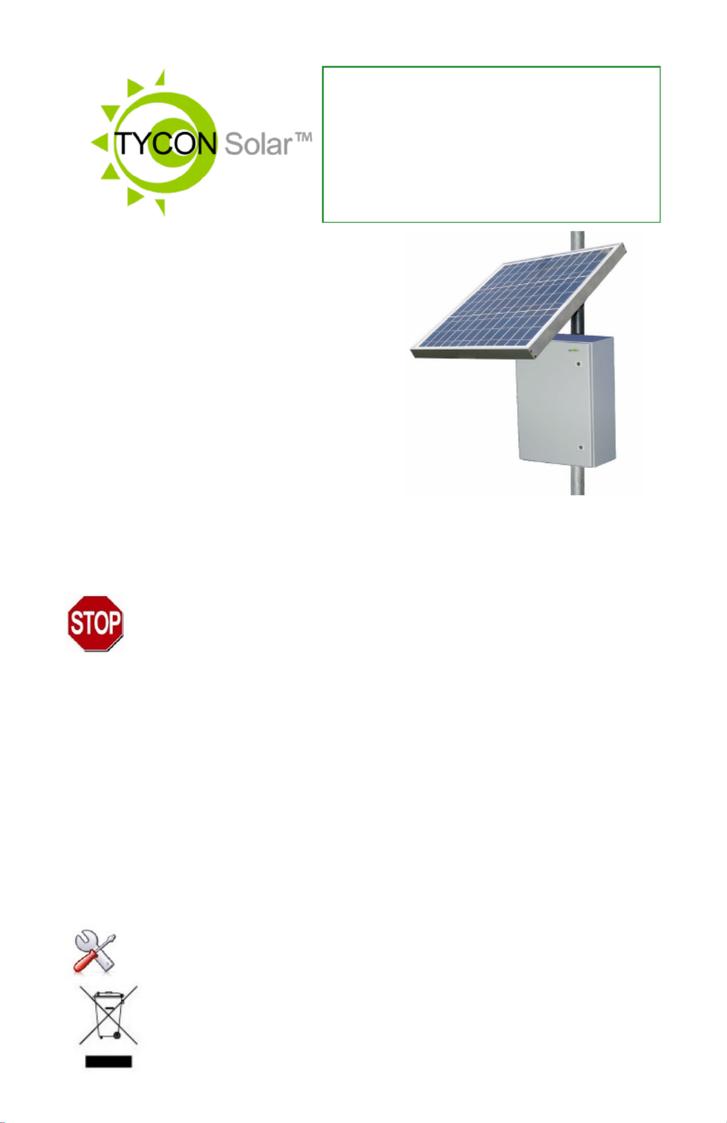
RemotePro®
Remote Power System
▫Wireless Base Stations
and Client Devices
▫Surveillance Cameras
▫Remote Sensors
▫Remote Lighting
▫Off Grid Electronics
Congratulations! on your purchase of the RemoteProoffgrid ™ -
remote power system. Please take a moment to review this Qwik
Install Guide before assembly or battery installation.
DANGER! Avoid Powerlines!
You Can Be Killed!
When following the instructions in this guide take extreme care
to avoid contact with overhead power lines, lights and power circuits.
Contact with power lines, lights or power circuits may be fatal. We rec-
ommend to install no closer than 20 feet to any power lines.
Safety: For your own protection, follow these safety rules.
▫Perform as many functions as possible on the ground
▫Do not attempt to install on a rainy, windy or snowy day or if
there is ice or snow accumulation at the install site or if the
site is wet.
▫Make sure there are no people, pets, etc. below when you are
working on a roof or ladder.
Recommended Tools: Phillips Screwdriver, 13mm and 10mm
Wrench, nut driver, Flat Blade Screwdriver5/16”
Please help preserve the environment and return
used batteries to an authorized depot
Product specificaties
| Merk: | Tycon Systems |
| Categorie: | Zonnepaneel |
| Model: | RemotePro |
| Kleur van het product: | Zwart |
| Gewicht: | 62000 g |
| Accu/Batterij voltage: | 24 V |
| Uitgangsspanning (max): | 24 V |
| Batterijen inbegrepen: | Ja |
| Batterijtechnologie: | Sealed Lead Acid (VRLA) |
| Nominaal vermogen: | 320 W |
Heb je hulp nodig?
Als je hulp nodig hebt met Tycon Systems RemotePro stel dan hieronder een vraag en andere gebruikers zullen je antwoorden
Handleiding Zonnepaneel Tycon Systems

24 Juli 2023
24 Juli 2023
Handleiding Zonnepaneel
Nieuwste handleidingen voor Zonnepaneel
13 Juli 2026
2 Juli 2026
22 Juni 2026
15 Juni 2026
24 Maart 2026
13 Maart 2026
12 Maart 2026
7 Maart 2026
27 Februari 2026
26 Februari 2026