Toa RM-300X Handleiding
Toa
Niet gecategoriseerd
RM-300X
Bekijk gratis de handleiding van Toa RM-300X (77 pagina’s), behorend tot de categorie Niet gecategoriseerd. Deze gids werd als nuttig beoordeeld door 48 mensen en kreeg gemiddeld 3.5 sterren uit 24.5 reviews. Heb je een vraag over Toa RM-300X of wil je andere gebruikers van dit product iets vragen? Stel een vraag
Pagina 1/77

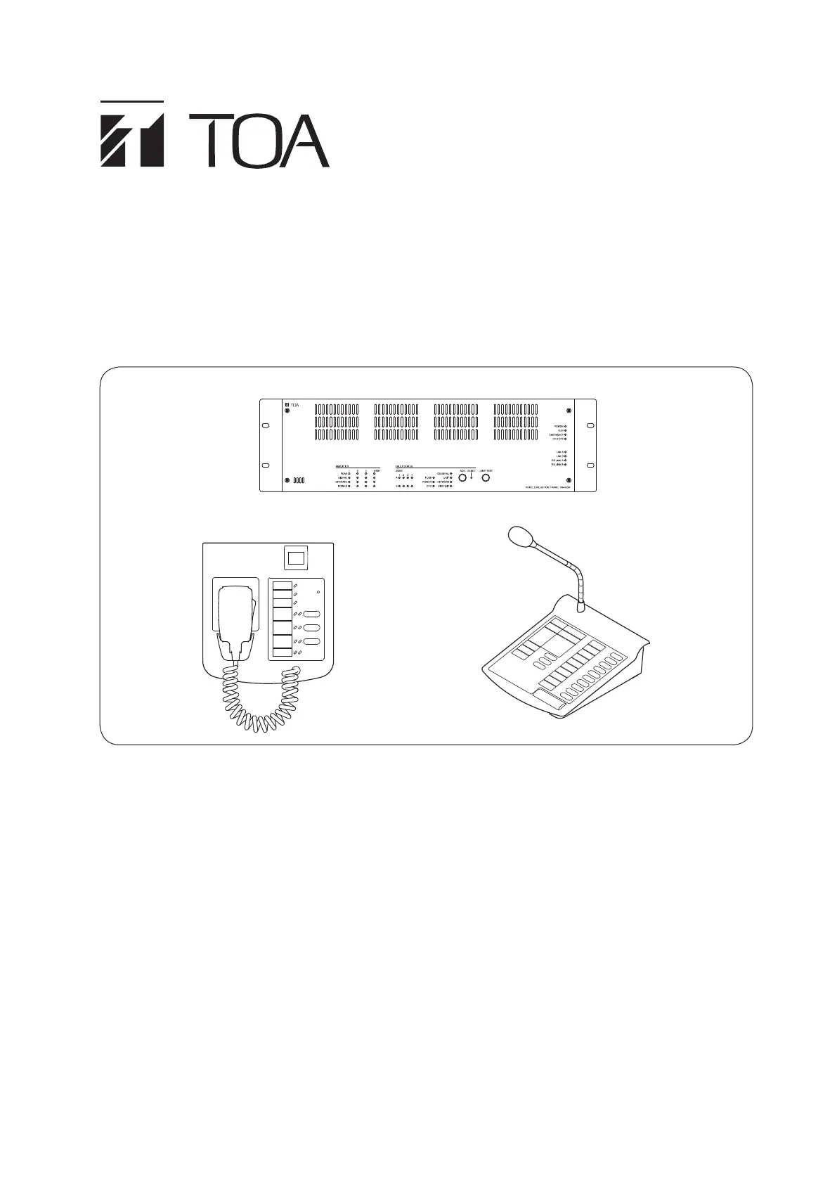
OPERATING INSTRUCTIONS
INTEGRATEd VOICE EVACUATION SYSTEM
VX-3000 SERIES
RM-200SF
VX-3004F
RM-300X
Thank you for purchasing TOA's Integrated Voice Evacuation System.
Please carefully follow the instructions in this manual to ensure long, trouble-free use of your equipment.

2
TABLE OF CONTENTS
Chapter 1 : NOMENCLATURE
1. VX-3004F, VX-3008F, ANd VX-3016F
VOICE EVACUATION FRAME ............................................................... 1-2
2. RM-200SF FIREMAN’S MICROPHONE
ANd RM-320F REMOTE MICROPHONE EXTENSION ........ 1-5
2.1. RM-200SF .......................................................................................................... 1-5
2.2. RM-320F ............................................................................................................ 1-7
3. RM-300X REMOTE MICROPHONE ANd
RM-210F REMOTE MICROPHONE EXTENSION
..................... 1-8
3.1. RM-300X ............................................................................................................ 1-8
3.2. RM-210F ............................................................................................................ 1-9
Chapter 2 : INdICATOR STATUS OF REMOTE MICROPHONES
1. RM-200SF FIREMAN’S MICROPHONE ANd
RM-320F REMOTE MICROPHONE EXTENSION
..................... 2-2
1.1. Indicator State at the Time of Zone Selection .................................................... 2-2
1.2. Talk Key Indicators ............................................................................................ 2-3
1.3. Indicator State at the Time of Base Pattern Change ........................................ 2-4
1.4. Indicator State at the Time of General-Purpose Broadcast Pattern ................. 2-4
1.5. Indicator State at the Time of General/BGM Broadcast ................................... 2-5
1.6. Indicator State at the Time of RM Broadcast Status Display ............................ 2-5
1.7. Indicator State at the Time of Lamp Test ........................................................... 2-6
1.8. Indicator State at the Time of Failure Output Receipt ........................................ 2-7
1.9. Indicator State at the Time of Failure Output Reset .......................................... 2-8
1.10. Indicator State at the Time of Emergency Broadcast Pattern Start ................ 2-9
1.11. Indicator State at the Time of Emergency Broadcast Pattern Stop ................ 2-10
1.12. Indicator State at the Time of Emergency Broadcast Pattern Start/Stop ....... 2-11
1.13. Indicator State at the Time of Emergency Sequence Stop ............................ 2-12
1.14. Indicator State at the Time of Emergency Sequence Phase Shift ................. 2-13
1.15. Indicator State at the Time of Emergency Reset ............................................ 2-14
1.16. Indicator State at the Time of Audio Monitor .................................................. 2-15
1.17. Indicator State at the Time of Intended Control Input ..................................... 2-15
1.18. Indicator State at the Time of Intended Control Output (Pulse) ...................... 2-16
1.19. Indicator State at the Time of Intended Control Output (Level) ...................... 2-16
1.20. Indicator State at the Time of Zone Volume Adjustment (Pulse) ................... 2-17
1.21. Indicator State at the Time of Input Volume Adjustment (Pulse) .................... 2-18
1.22. Indicator State at the Time of Emergency Warning Broadcast ...................... 2-19
2. RM-300X REMOTE MICROPHONE ANd
RM-210F REMOTE MICROPHONE EXTENSION
................... 2-20
2.1. Indicator State at the Time of Zone Selection .................................................. 2-20
2.2. Talk Key Indicators ........................................................................................... 2-21
2.3. Indicator State at the Time of Base Pattern Change ....................................... 2-21
2.4. Indicator State at the Time of General-Purpose Broadcast Pattern ................ 2-22

3
2.5. Indicator State at the Time of General/BGM Broadcast .................................. 2-22
2.6. Indicator State at the Time of RM Broadcast Status Display ........................... 2-23
2.7. Indicator State at the Time of Lamp Test ......................................................... 2-23
2.8. Indicator State at the Time of Failure Output Receipt ...................................... 2-24
2.9. Indicator State at the Time of Failure Output Reset ......................................... 2-25
2.10. Indicator State at the Time of Emergency Broadcast Pattern Start ............... 2-26
2.11. Indicator State at the Time of Emergency Broadcast Pattern Stop ................ 2-27
2.12. Indicator State at the Time of Emergency Broadcast Pattern Start/Stop ....... 2-28
2.13. Indicator State at the Time of Emergency Sequence Stop ............................ 2-29
2.14. Indicator State at the Time of Emergency Sequence Phase Shift ................ 2-30
2.15. Indicator State at the Time of Emergency Reset ............................................ 2-31
2.16. Indicator State at the Time of Audio Monitor ................................................. 2-32
2.17. Indicator State at the Time of Intended Control Input .................................... 2-32
2.18. Indicator State at the Time of Intended Control Output (Pulse) .................... 2-33
2.19. Indicator State at the Time of Intended Control Output (Level) ..................... 2-33
2.20. Indicator State at the Time of Zone Volume Adjustment (Pulse) .................. 2-34
2.21. Indicator State at the Time of Input Volume Adjustment (Pulse) ................... 2-35
2.22. Indicator State at the Time of Emergency Warning Broadcast ..................... 2-36
Chapter 3 : OPERATION
1. BGM ANd GENERAL BROAdCAST ................................................ 3-2
1.1. Broadcasting from the RM-200SF, RM-300X, RM-320F, and RM-210F ........... 3-2
1.2. Assignment Example ........................................................................................ 3-2
1.3. Operation Examples ......................................................................................... 3-3
2. EMERGENCY wARNING BROAdCAST ....................................... 3-9
3. EMERGENCY BROAdCAST ................................................................ 3-10
3.1. Typical System Examples ................................................................................ 3-10
3.2. Remote Microphone Operation Example ........................................................ 3-12
4. MAkING ALL-ZONE EMERGENCY BROAdCAST ................ 3-15
4.1. Priority Control of the All-Zone Emergency Broadcast ..................................... 3-15
4.2. Making All-zone Emergency Broadcast from the RM-300X ............................ 3-16
4.3. Making All-zone Emergency Broadcast from the RM-200SF .......................... 3-17
5. dETECTING FAULT ................................................................................... 3-18
5.1. Fault Detection Setting Example ...................................................................... 3-18
5.2. Case Example of Malfunction .......................................................................... 3-19
5.3. Remote Microphone's Operation Example ..................................................... 3-20
5.4. VX-3004F's Operation Example ...................................................................... 3-21
5.5. Example of Executing the Failure Reception and Failure Reset
by Way of the Control Input Terminals ............................................................ 3-22
6. LAMP TEST .................................................................................................... 3-23
6.1. Remote Microphone's Operation Example ...................................................... 3-23
6.2. VX-3004F's Operation Example ...................................................................... 3-24
7. OTHER FUNCTIONS ................................................................................. 3-25
7.1. Audio Monitor ................................................................................................... 3-25
7.2. Intended Control Input Operation .................................................................... 3-26
Product specificaties
Merk: | Toa |
Categorie: | Niet gecategoriseerd |
Model: | RM-300X |
Kleur van het product: | Zwart |
Breedte: | 190 mm |
Diepte: | 215 mm |
Hoogte: | 76.5 mm |
Materiaal behuizing: | Acrylonitrielbutadieenstyreen (ABS) |
Kleur behuizing: | Zwart |
Duurzaamheidscertificaten: | CE |
Ingangsspanning: | 15 - 40 V |
Frequentiebereik: | 100 - 20000 Hz |
Naleving van duurzaamheid: | Ja |
Signaal/ruis-verhouding: | 60 dB |
Stroomverbruik (typisch): | - W |
Bedrijfstemperatuur (T-T): | 0 - 40 °C |
Relatieve vochtigheid in bedrijf (V-V): | 35 - 80 procent |
Type product: | Noodmicrofoon |
Totale harmonische vervorming plus ruis (1 kHz): | 1 procent |
Heb je hulp nodig?
Als je hulp nodig hebt met Toa RM-300X stel dan hieronder een vraag en andere gebruikers zullen je antwoorden
Handleiding Niet gecategoriseerd Toa
24 Mei 2025
24 Mei 2025
21 Maart 2025
10 December 2024
18 September 2024
3 September 2024
3 September 2024
9 Juli 2024
9 Juli 2024
9 Juli 2024
Handleiding Niet gecategoriseerd
- Boehringer Ingelheim
- Pelican
- Plastkon
- DMax
- Stages
- Bavaria By Einhell
- BikeLogger
- Royal Catering
- XS Power
- Gree
- Iiyama
- Cartoni
- Gymform
- Xterra
- Dot Line
Nieuwste handleidingen voor Niet gecategoriseerd
30 Juli 2025
30 Juli 2025
30 Juli 2025
30 Juli 2025
30 Juli 2025
30 Juli 2025
30 Juli 2025
30 Juli 2025
30 Juli 2025
30 Juli 2025