Supermicro X10SLE-F Handleiding
Supermicro Niet gecategoriseerd X10SLE-F
Bekijk gratis de handleiding van Supermicro X10SLE-F (1 pagina’s), behorend tot de categorie Niet gecategoriseerd. Deze gids werd als nuttig beoordeeld door 14 mensen en kreeg gemiddeld 5.0 sterren uit 4 reviews. Heb je een vraag over Supermicro X10SLE-F of wil je andere gebruikers van dit product iets vragen? Stel een vraag
Pagina 1/1
S
UPERMICR
R
ContaCtnformatIonI
MNL-1486-QRG R. 1.00ev
•www.supermicro.com(Email:support@supermicro.com)
•Manuals:http://www.supermicro.com/support/manuals
•Drivers&Utilities:ftp://ftp.supermicro.com
•Safety:http://www.supermicro.com/about/policies/safety_information.cfm
© 2013 Supermicro Computer Inc. All rights reserved. Reproduction of this document whether in part or in whole is strictly prohibited without Supermicro's written
consent. All Trademarks are property of their respective entities. All information provided is deemed accurate at the time of printing; however, it is not guaranteed.
P C - BaCkageontentsulk
X10sle-f/Hf
Q r g uICkeferenCeuIder. 1.00ev
•One(1)QuickReferenceGuide
LED Indicators
Connectors
DIMM Memory Installation
Jumpers, Connectors and LED Indicators
Memory Support
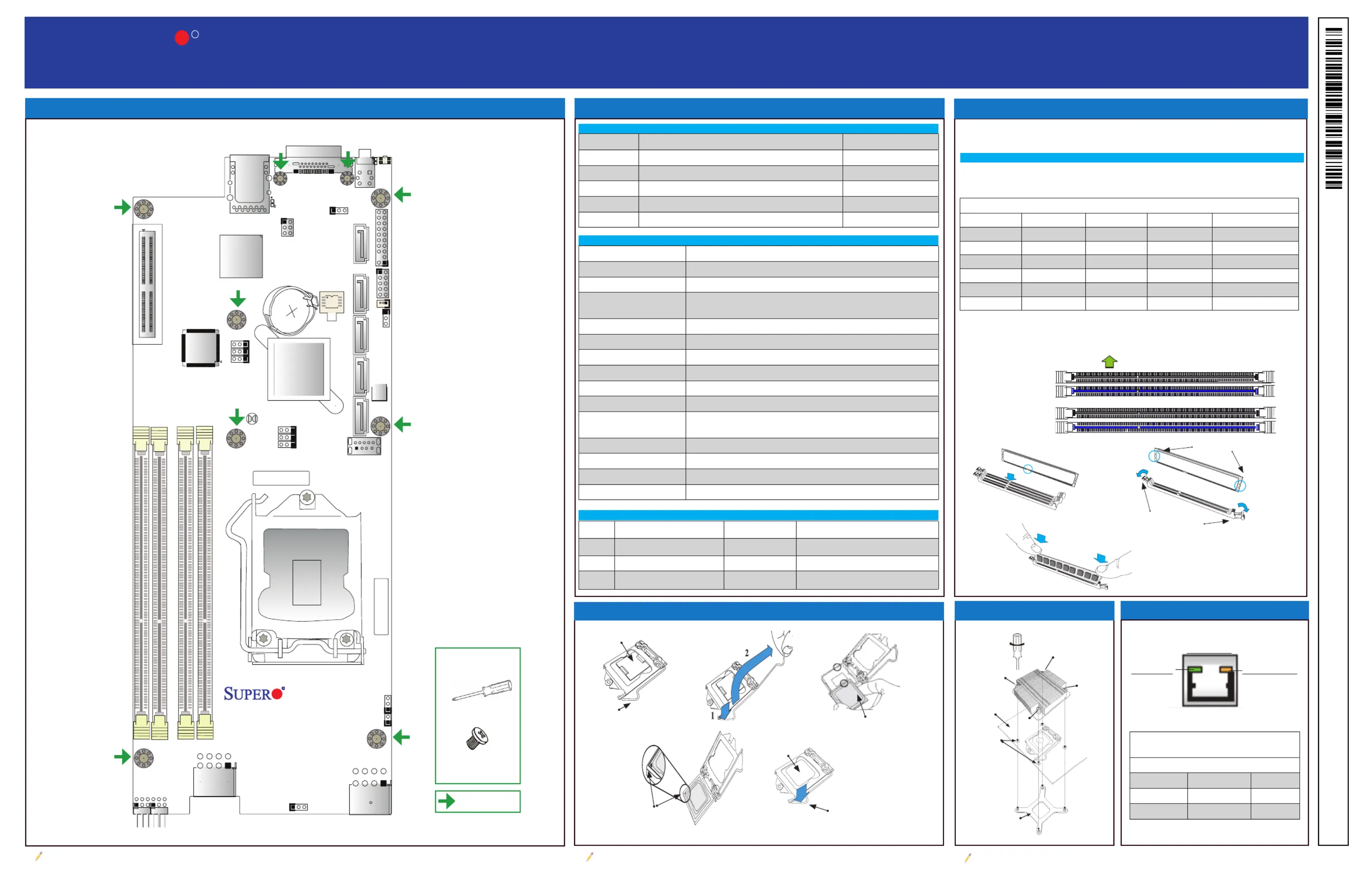
Motherboard Layout and Features
Jumpers
Note: Graphics shown in this quick reference guide are for illustration only. Your components may or may not look exactly the same as drawings shown in this guide.
Note: Refer to Chapter 1 of the User Manual for detailed information on jumpers, connectors,
and LED indicators.
Note: Refer to Chapter 2 of the User Manual for detailed information on memory support and CPU/
motherboard installation instructions.
= mounting hole
I-SATA4
JSD1JTPM1
JBR1
JPV1
JWD1
JPB1
JPME2
JPME1
J19
JPG1
J18
J22
JBT1
SW1
LED5
LED6
JKVM1
JUIDB1
JPWR2
I-SATA1I-SATA0I-SATA3I-SATA2
JP16
JP1
JP18
JP17
BAR CODE
MAC CODE
Battery
USB3.0-0
IPMI_LAN
UID
MICRO-LPCI-E 3.0 X8P
X10SLE-F/HF
Rev. 1.00
PWR
DIMMB2
DIMMB1
DIMMA2
DIMMA1
CPU
BIOS
PCH
BMC
AST2400
Intel LP
C226/C224
JumperDescriptionDefault
JBT1CMOS Clear(See Chpt. 2)
JPG1VGA EnablePins 1-2 (Enabled)
JPME1ME RecoveryPins 1-2 (Normal)
JPME2Manufacture Mode SelectPins 1-2 (Normal)
JWD1Watch Dog Timer EnablePins 1-2 (RST)
ConnectorDescription
BatteryOnboard Battery
IPMI_LANIPMI_Dedicated LAN
JKVM1USB (x2)/VGA (Monitor)/COM (UART) Connector for Remote Console
Redirection or Remote Network Interface
JP16Power Output for Hard Disk Drive (12V and 5V)
JP17Motherboard Interface to PDB
JP18Motherboard Interface to PDB
JPWR2SMC-Proprietary Power Connector
JSD1SATA DOM (Device_On_Module) Power Connector
JTPM1Trusted Platform Module/Port 80 Connector
I-SATA0 - I-SATA4(Intel PCH) Serial ATA Ports 0-4 (I-SATA0-3: SATA 3.0 Ports, I-SATA4:
SATA 2.0 Port)
Micro-LP PCI-E SlotSMC-Proprietary Micro Low-Prole (LP) PCI-Express 3.0 x8 Slot
SW1Power Switch/LED Indicator
UIDUnit Identier (UID) Button (JUIDB)
USB2, USB3 (3.0)Internal Type A USB 3.0
The X10SLE-F/-HF supports up to 32GB of Unbuffered (UDIMM) DDR3 ECC
1600/1333/1066 MHz VLP (Very Low Prole) memory in 4 slots.
Memory Population Guidelines
Please follow the table below when populating the X10SLE-F/HF.
Recommended Population (Balanced)
DIMMA2DIMMB2DIMMA1DIMMB1Total System Memory
2GB DIMM2GB DIMM4GB
2GB DIMM2GB DIMM2GB DIMM2GB DIMM8GB
4GB DIMM4GB DIMM8GB
4GB DIMM4GB DIMM4GB DIMM4GB DIMM16GB
8GB DIMM8GB DIMM16GB
8GB DIMM8GB DIMM8GB DIMM8GB DIMM32GB
Insert the desired number of DIMMs into the memory slots, starting with DIMMA2
(Channel A, Slot 2). For the system to work properly, please use the memory
modules of the same type and speed in the same motherboard.
Channel A Slot 1
Channel A Slot 2
(Blue Slot)
Channel B Slot 1
Channel B Slot 2
(Blue Slot)
Towards the CPU
Notches
Release Tabs
Press both notches
straight down into
the memory slot.
Linkivi LEDActty LED
IPMI LAN
IPMI LAN Link LED (Left) &
Activity LED (Right)
Color/State Denition
Link (Left)Green: Solid100 Mbps
Amber: Solid1000 Mbps
Activity (Right)Yellow BlinkingActive
Tools Needed:
Screwdriver
Phillips screws (9)
CPU Installation
CPU Properly
Installed
Load Lever Locked
into Place
Load Lever
Load Plate
Pin 1
North Center Edge
Heatsink Installation
Screw#1
Screw#2
Screw#3
Screw#4
Motherboard
Mounting Holes
Heatsink Bracket
IPMI LAN Port LED
LEDDescriptionColor/StateStatus
LE5BMC Heartbeat LEDGreen: BlinkingBMC Functions Normally
LED5Power Fail/Fan Fail/OverheatRed: OnPower Fail, Fan Fail or Overheating
LED6UID LEDBlue: OnUnit Identied
Product specificaties
| Merk: | Supermicro |
| Categorie: | Niet gecategoriseerd |
| Model: | X10SLE-F |
| Breedte: | 117 mm |
| Diepte: | 297 mm |
| Ethernet LAN: | Ja |
| Temperatuur bij opslag: | -40 - 70 °C |
| Aantal poorten USB 3.2 Gen 1 (3.1 Gen 1) Type A: | 1 |
| Processor socket: | LGA 1150 (Socket H3) |
| Processorfabrikant: | Intel |
| Maximum intern geheugen: | 32 GB |
| On-board graphics adapter model: | Aspeed AST2400 |
| Luchtvochtigheid bij opslag: | 5 - 95 procent |
| ECC: | Ja |
| Chipset moederbord: | Intel® C224 |
| RAID support: | Ja |
| Ondersteunde opslagstationinterfaces: | SATA III |
| Component voor: | Server |
| Geheugen voltage: | 1.5 V |
| LAN controller: | Realtek RTL8211E |
| Soorten RAID: | 0, 1,5, 10 |
| PCI Express x8 (Gen 3.x) slots: | 1 |
| Aantal SATA III connectors: | 4 |
| Compatibele processors: | Intel® Pentium® |
| Aantal ondersteunde processoren: | 1 |
| Intel® Xeon series: | E3-1200 |
| Maximum UDIMM geheugen: | 32 GB |
| Aantal DIMM sloten: | 4 |
| Ondersteunend DIMM module capaciteiten: | 1GB, 2GB, 4GB, 8GB |
| Ondersteunde geheugen types: | DDR3-SDRAM |
| Wifi: | Nee |
| Bedrijfstemperatuur (T-T): | 0 - 50 °C |
| Relatieve vochtigheid in bedrijf (V-V): | 8 - 90 procent |
| Supported memory clock speeds: | 1600 MHz |
| BIOS type: | AMI |
| ACPI version: | 5.0 |
| Ondersteuning voor parallel processing: | Niet ondersteund |
| Aansluitingen voor behuizingsventilatoren: | 5 |
| USB 3.2 Gen 1 (3.1 Gen 1)-aansluitingen: | 2 |
| TPM connector: | Ja |
| Chassis intrusion aansluiting: | Ja |
| IPMI LAN (RJ-45) port: | Ja |
Heb je hulp nodig?
Als je hulp nodig hebt met Supermicro X10SLE-F stel dan hieronder een vraag en andere gebruikers zullen je antwoorden
Handleiding Niet gecategoriseerd Supermicro

6 April 2026
13 Maart 2026
13 Maart 2026
9 Februari 2026
21 Januari 2026
20 Januari 2026
19 Januari 2026
19 Januari 2026
13 Januari 2026
12 Januari 2026
Handleiding Niet gecategoriseerd
Nieuwste handleidingen voor Niet gecategoriseerd
23 Juli 2026
23 Juli 2026
23 Juli 2026
23 Juli 2026
23 Juli 2026
23 Juli 2026
23 Juli 2026
23 Juli 2026
23 Juli 2026
22 Juli 2026