Supermicro SuperServer E403-9D-16C-FN13TP Handleiding
Supermicro Niet gecategoriseerd SuperServer E403-9D-16C-FN13TP
Bekijk gratis de handleiding van Supermicro SuperServer E403-9D-16C-FN13TP (1 pagina’s), behorend tot de categorie Niet gecategoriseerd. Deze gids werd als nuttig beoordeeld door 70 mensen en kreeg gemiddeld 4.8 sterren uit 3 reviews. Heb je een vraag over Supermicro SuperServer E403-9D-16C-FN13TP of wil je andere gebruikers van dit product iets vragen? Stel een vraag
Pagina 1/1
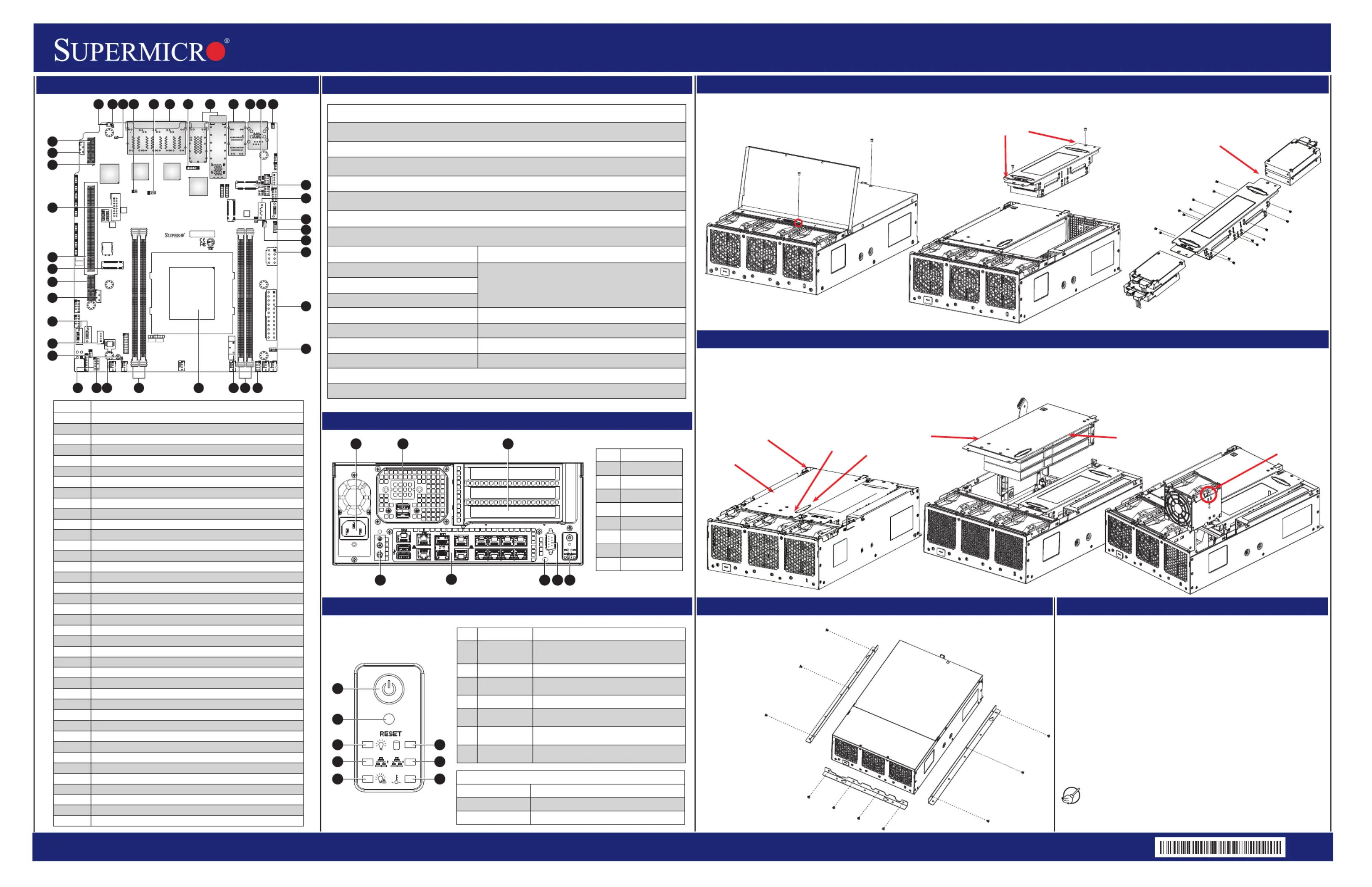
SuperServer E403-9D-4C/8CN/12C/14C/14CN/16C-FN13TP Quick Reference Guide
http://www.supermicro.comMNL-2208-QRG
Rev. 1.0
PlndlastHaic es
Installing
Hard Drives
The hard drive cage must be removed
from the chassis before installing the
hard drives.
Caution
Mounting the Chassis on the Wall
The CSE-E403iF supports up to three PCI-E slots. These slots are installed on a riser car and must be installed into the system to provide expansion capability.
Components of the Expansion Card Module
Accessing the Main System
For more information go to: http://www.supermicro.com/support
Always be sure all power supplies for this system have the same
power output. If mixed power supplies are installed, the system
will not operate.
IMPORTANT: See installation instructions and safety warning
before connecting system to power supply.
http://www.supermicro.com/about/policies/safety_information.cfm
! SAFETY INFORMATION
To reduce risk of electric shock/damage to equipment, disconnect
power from server by disconnecting all power cords from electrical
outlets.
If any CPU socket empty, install protective plastic CPU cap.
! WARNING:
! WARNING:
Please clean the dust filters regularly
Attach the three wall mount
brackets to the chassis using
the ten M4xL4 screws.
The mounting bracket along
the I/O panel is pre-
attached.
After disconnecting power, flip open the fan cover, remove the screw that has been exposed. Slightly slide the system cover towards the fans.
Lift both segments of the top cover off the chassis.
1. Power down the system and remove the AC power cord and the chassis cover.
2. Remove the screw as shown above and set aside.
3. Pull the locking lever up to release the expansion card module.
4. Pull the expansion card module upward with the aid of the plastic handle.
Please refer to user manual for
more information.
Expansion Card
Module
Remove this
screw
Locking Lever
Plastic Handle
Expansion Card
Module
Expansion Card
(optional)
Press the latch
Accessing the System
Installing or Replacing the Riser Cards and Fans
Front View and Features
Control Panel
Chassis
CSE-E403iF
Processors
Socket Type
Intel
®
Xeon
®
D-2123IT, Intel
®
Xeon
®
D-2146NT, Intel
®
Xeon
®
D-2163IT, Intel
®
Xeon
®
D-2173IT,
Intel
®
Xeon
®
D-2177NT, and Intel
®
Xeon
®
D-2183IT
FCBGA2518
Memory
Chipset
Supports up to 256GB of ECC/non ECC RDIMM or 512GB of ECC LRDIMM DDR4 memory with
speeds of up to 2667MHz (D-2177NT) in four DIMM slots
System on Chip
Expansion Slots
Storage Drives
Two PCI-E 3.0 p1-x16 or two PCI-E 3.0 p1-x8 + one PCI-E 3.0 p1-x16 (FH3/4L) slots
One M.2 M-Key 2280/22110, One M.2 B-Key 3042, One M.2 E-Key 2230
Four internal SATA3 2.5" drive bays
Input/Output
Power
600W AC multi-output PFC Gold Certified power supply
Cooling
Three 80x80mm PWM redundant fans
Dimensions
Compact Box 2.5U (WxHxD) 10.5 x 4.3 x 16 in. (267 x 109 x 406 mm)
Network
Four SATA3 (6Gbps) ports supporting RAID 0, 1, 5, 10
USB: two USB 3.0 ports (front), two USB 2.0 ports (front)
Serial Port: one COM via RJ45
Video: one VGA port
Two RJ45 GbE LAN ports, nine RJ45 10GbE LAN ports, two 10G SFP+ LAN ports, and one RJ45
dedicated IPMI LAN port
System FeaturesBoard Layout
ItemDescription
1Power Input
2USB ports
3PCI Slots
4Ground
5I/O Front Panel
6
UID
7VGA Port
8Control Panel
Features
Power button
Reset Button
Power LED
HDD LED
NIC LED
Information LED
Item
1
2
3
4
5
6
7Overheat LED
Description
The main power switch applies or removes
primary power from the power supply to the
server but maintains standby power.
System reset button
Indicates power is being supplied to the
system power supply units.
Indicates hard disk drive activity when flashing.
Indicates network activity on the LAN when
flashing.
Alerts operator to several states, as noted in
the table on the next page.
If this indicator is continuously on and red, an
overheat condition has occurred.
StatusDescription
Information LED
Blinking red (1Hz)
Blinking red (0.25Hz)
Fan failure. Check for an inoperative fan.
Power failure. Check for a non-operational power
RESET
1
123
CMOS Clear
Trusted Platform Module (TPM)/Port 80
TPM Enable/Disable
4-pin HDD Power
SATA3.0 Ports
CPU
Power LED
Unit Identifier Switch
UID LED
10G SFP+ / 10G LAN / 1G LAN Ports (from I350)
Software-Defined Pins (For I350 LAN2)
1G LAN Ports(from I350)
1G LAN Ports(from I210) / Dedicated IPMI LAN Port
COM1/USB3.1
LAN JBMActivity LED
Disable Dedicated IPMI/Shared LAN
M.2 Slot E-Key 2230 (USB2.0 / PCI-E x1)
SATA3.0
M.2 Slot M-Key 2280/22110 (SATA3.0 / PCI-E x4)
RAID Key
SATA DOM Power
12V 8-pin DC Power
24-pin ATX Power
Standby Power
Disable IPMI Shared LAN
M.2 SMBus Enable/Disable
Description
Overheat/Power Fail/Fan Fail LED
Serial Link General Purpose I/O
DIMMA1~DIMMB1
Onboard Battery
No.
DIMMD1~DIMME1
BMC
System Management Bus (for IPMI only)
WIO
M.2 Slot B-Key 2242/3042, PCI-E 3.0 X2 / S-SATA4
VGA
Non-volatile Memory (NVMe) I2C
WIO
29
30
31
26
1
2
4
5
6
7
8
9
10
11
12
13
14
15
16
17
18
19
20
21
22
23
24
3
25
27
28
39
36
32
33
34
35
37
38
WIO, PCI-E X16+X16
FAN4
FAN3
FAN1
FAN2
JD1
JF1
FANA
JSD1
JIPMB1
JNVI2C1
JTGLED2
JTGLED1
JBT1
JTPM1
JPI2C1
JPWR1
JBM1
JBM2
JLANLED1
JLANLED3
S-SGPIO1
JLANLED2
JSTBY1
LEDM1
LEDT4LEDT2
JPG1
J1
JVRM1JPL2JPL3
JPT1
JSMB1JI2C1JI2C2JWD1JPME2
JPUSB1
JPL1
MH1
MH3
MH7
MH2
MH4
MH6
MH5
BT1
JMD2_SRW1
JMD1_SRW1
LED3
LED1
JMD3_SRW1
LED2
LEDT3
SSA3AT
JSIM1
JGP1
JPV1
S-SA1AT
JVGA1
COM2
JRK1
S-SA0AT
JMD1: M.2-H
JSDP3
JSDP2
JSDP1
S-SA2AT
JPW1
LEDT1
PRESS FIT
CA
CACA
A
C
A
C
CACA
DESIGNED IN USA
BAR CODE
X11SDW-4C-TP13F
REV:1.01
LAN 1
COM1
USB 4/5
USB 2/3
USB 0/1
2-3:DISABLE
JPT1:TPM
1-2:ENABLE
: PCI-E X16+X16
JSXB1C
JSXB1B
JSXB1A
CPU
JPL3:
LAN 6/7/8/9
1-2:ENABLE
2-3:DISABLE
JPL2:
2-3:DISABLE
LAN 2/3/4/5
1-2:ENABLE
PCI-E 3.0 X1
JMD3:M.2-P
JMD2:M.2-H
PCI-E 3.0 X2 / S-SA4AT
UID
LAN 2/3/4/5/6/7/8/9
PCI-E 3.0 X4 / I-SA4AT
LAN 12/13
LAN 10/11
IPMI_LAN
LED
HDD
NIC1
ON
PWR
RST
X
FF
OH
NIC2
LED
PWR
JF1:
JD1:
1-
4-7:SPEAKER
3:PWR LED
DIMMA1
DIMMB1
DIMME1
DIMMD1
JL1
JPH1
4
5
68
1
2
3
5
6
4
5
7
13
16
18
19
20
17
15
7
26272821
222425
23
29
30
32
33
34
35
36
37
38
39
31
14
891012123456711
Product specificaties
| Merk: | Supermicro |
| Categorie: | Niet gecategoriseerd |
| Model: | SuperServer E403-9D-16C-FN13TP |
| Kleur van het product: | Zwart |
| Gewicht: | 7700 g |
| Breedte: | 267 mm |
| Diepte: | 406 mm |
| Hoogte: | 109 mm |
| Frequentie van processor: | 2.2 GHz |
| Processorfamilie: | Intel® Xeon® |
| Processormodel: | D-2183IT |
| Aantal processorkernen: | 16 |
| Inclusief besturingssysteem: | Nee |
| Ethernet LAN: | Ja |
| Aantal USB 2.0-poorten: | 2 |
| VGA (D-Sub)poort(en): | 1 |
| Netvoeding: | 600 W |
| Intern geheugen: | - GB |
| Intern geheugentype: | DDR4-SDRAM |
| Temperatuur bij opslag: | -40 - 70 °C |
| Aantal poorten USB 3.2 Gen 1 (3.1 Gen 1) Type A: | 2 |
| Processor cache: | 22 MB |
| Thermal Design Power (TDP): | 100 W |
| Maximum intern geheugen: | 512 GB |
| Totale opslagcapaciteit: | - GB |
| Soort optische drive: | Nee |
| Luchtvochtigheid bij opslag: | 5 - 95 procent |
| Maximale turbofrequentie van processor: | 3 GHz |
| ECC: | Ja |
| Geheugenslots: | 4 |
| Ethernet interface type: | 10 Gigabit Ethernet |
| Aantal geïnstalleerde processoren: | 1 |
| PCI Express x16 (Gen 3.x) slots: | 2 |
| HDD omvang: | - " |
| Maximale opslagcapaciteit: | - TB |
| PCI Express x8 (Gen 3.x) slots: | 3 |
| Aantal hoofdvoedingen: | 1 |
| Aantal SATA III connectors: | 4 |
| Bedrijfstemperatuur (T-T): | 10 - 40 °C |
| Relatieve vochtigheid in bedrijf (V-V): | 8 - 90 procent |
| BIOS type: | AMI |
| Intelligent Platform Management Interface (IPMI) support: | Ja |
Heb je hulp nodig?
Als je hulp nodig hebt met Supermicro SuperServer E403-9D-16C-FN13TP stel dan hieronder een vraag en andere gebruikers zullen je antwoorden
Handleiding Niet gecategoriseerd Supermicro

6 April 2026
13 Maart 2026
13 Maart 2026
9 Februari 2026
21 Januari 2026
20 Januari 2026
19 Januari 2026
19 Januari 2026
13 Januari 2026
12 Januari 2026
Handleiding Niet gecategoriseerd
Nieuwste handleidingen voor Niet gecategoriseerd
23 Juli 2026
23 Juli 2026
23 Juli 2026
23 Juli 2026
23 Juli 2026
23 Juli 2026
23 Juli 2026
23 Juli 2026
23 Juli 2026
22 Juli 2026