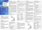
Siemens RCC10 Handleiding
Siemens
Thermostaat
RCC10
Bekijk gratis de handleiding van Siemens RCC10 (10 pagina’s), behorend tot de categorie Thermostaat. Deze gids werd als nuttig beoordeeld door 84 mensen en kreeg gemiddeld 5.0 sterren uit 42.5 reviews. Heb je een vraag over Siemens RCC10 of wil je andere gebruikers van dit product iets vragen? Stel een vraag
Pagina 1/10

CE1N3021en
2021-12-08
Smart Infrastructure
3
021
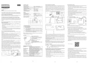
Room Temperature Controllers
RCC10…
for two-pipe fan coil units
Output for on / off valve actuator
Outputs for three-speed fan
Control depending on the room or return air temperature (RCC10)
Automatic heating / cooling changeover
Operating modes of RCC10: normal, energy saving and frost protection mode or
OFF
Operating modes of RCC10.1: normal and energy saving mode or OFF
Operating mode changeover input for remote control
Function for avoiding damage resulting from moisture (RCC10.1)
Selectable control parameters (RCC10)
Operating voltage AC 230 V
Use
Typical use:
Control of the room temperature in individual rooms that are heated or cooled with
two-pipe fan coil units.
For opening or closing a valve and for switching a three-speed fan.
Suitable for use in systems with
automatic heating / cooling changeover
continuous heating or cooling operation.

2/10
Siemens Room temperature controller CE1N3021en
Smart Infrastructure 2021-12-08
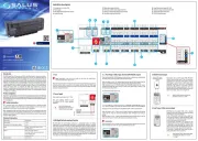
Functions
The controller acquires the room temperature with its integrated sensor or external
room temperature sensor (QAA32) or external return air temperature sensor (QAH11.1)
– if used (optional with the RCC10) – and maintains the setpoint by delivering control
commands to the 2-point-valve.
The switching differential with the
RCC10 is adjustable; it can be 1 or 4 K in heating mode and 0.5 or 2 K in cooling
mode
RCC10.1 is fixed; it is 2 K in heating mode and 1 K in cooling mode
The fan is switched to the selected speed via control output Q1, Q2 or Q3.
When the function “Temperature-dependent fan control” is activated (can be selected
with DIP switch no.1), the fan is switched on / off depending on the temperature, that is,
together with the valve.
It is switched off by
leaving the heating or cooling sequence, provided the function “Temperature-
dependent fan control” is activated, or
manually changing to standby , provided plant conditions do not call for frost
protection mode (only with the RCC10), or
activating an external operating mode changeover switch, provided plant conditions
do not call for energy saving or frost protection mode (only with the RCC10), or
turning the controller’s power supply off.
The heating or cooling valve receives the OPEN command via control output Y11 when
1. the measured room temperature lies by half the switching differential below the
setpoint (heating mode) or above the setpoint (cooling mode), and
2. the valve has been fully closed for more than one minute.
The heating or cooling valve receives the CLOSE command via control output Y11
when
1. the measured room temperature lies by half the switching differential above the
setpoint (heating mode) or below the setpoint (cooling mode), and
2. the valve has been fully open for more than one minute.
Note: control output Y12 delivers a control command which is inverted to the control
command at output Y11 and can be used for normally open valves
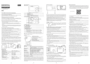
The RCC10 provides control either depending on the measured room temperature or
depending on the fan coil unit’s return air temperature. Changeover is automatic if a
QAH11.1 cable temperature sensor is connected.
Fan operation
Heating and
cooling mode
ON
OFF
Return air tempera-
ture

3/10
Siemens Room temperature controller CE1N3021en
Smart Infrastructure 2021-12-08
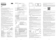
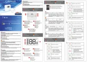
The water temperature acquired by the changeover sensor (QAH11.1 + ARG86.3) is
used by the controller to switch from heating to cooling mode, or vice versa. When the
water temperature lies above 28 °C, the controller switches to heating mode, below
16 °C it switches to cooling mode. If, immediately after switching on, the water tempera-
ture lies between the 2 changeover points, the controller will start in heating mode. The
water temperature is measured at minute-intervals and the operational status updated.
Heating mode Cooling mode Automatic changeover
SDH
Y11
W
SDC
Y11
W
CM
HM
M
16
28
CM Cooling mode TWWater temperature
HM Heating mode w Room temperature setpoint
M Operating mode Y11 Manipulated variable “Valve”
SDC Switching dierential “Cooling” T Room temperature
SDH Switching dierential “Heating”
The task of the changeover sensor is to initiate the change from heating to cooling
mode even if the two-port valves are shut down for a longer period of time. To ensure
this function, the valves are opened for one minute at 2-hour intervals during off hours.
(Note: this function is not effective when using thermal actuators)
The room temperature setpoint can be limited in increments of 1 K by making use of
the minimum and maximum limitation facility. Arbitrary setpoint readjustments can thus
be prevented.
Operating modes
The following operating modes are available:
Heating or cooling mode with automatic changeover and with manually selected fan
speed III, II or I. In normal operation, the controller maintains the adjusted setpoint.
The frost protection function is activated only when DIP switch no.4 is set to OFF.
Frost protection mode can be activated either
by manually switching to standby .
by activating the external operating mode changeover switch, provided DIP switch
no.2 is set to OFF
If the room temperature falls below 8 °C, the controller will automatically switch to frost
protection mode. In that case, the heating valve opens and the fan operates at the se-
lected speed. If the operating mode selector is in position standby , the fan will oper-
ate at speed I. The room temperature is maintained at a setpoint of 8 °C and the set-
point adjusted by the user will be ignored.
If frost protection mode is locked (DIP switch no.4 in position ON), standby is locked
also, which means that the controller will not switch to standby but to OFF:
In energy saving mode, the setpoint of heating is 16 °C and the setpoint of cooling
28 °C, independent of the position of the setpoint knob. This operating mode will be
activated when input D1 for operating mode changeover is active and DIP switch no.2
is set to ON.
Automatic
changeover
Purging function
Energy saver
Normal operation
Frost protection mode
(only with the RCC10)
Energy saving
mode
Product specificaties
| Merk: | Siemens |
| Categorie: | Thermostaat |
| Model: | RCC10 |
Heb je hulp nodig?
Als je hulp nodig hebt met Siemens RCC10 stel dan hieronder een vraag en andere gebruikers zullen je antwoorden
Handleiding Thermostaat Siemens

15 Oktober 2024

8 April 2024

17 Maart 2024

25 Februari 2024

10 Februari 2024

8 Februari 2024

7 Januari 2024

5 December 2023

21 November 2023

11 November 2023
Handleiding Thermostaat
- Busch-Jaeger
- Vaillant
- 2Heat
- EQ3
- Emko
- Arnold Rak
- Plugwise
- Nexa
- Nefit
- Tado
- Carel
- Carrier
- Landis Gyr
- POER
- Enda
Nieuwste handleidingen voor Thermostaat
31 Juli 2025

30 Juli 2025
29 Juli 2025
29 Juli 2025
28 Juli 2025
28 Juli 2025
28 Juli 2025
28 Juli 2025
28 Juli 2025
28 Juli 2025