ServSense 651CPSSI11LP Handleiding
ServSense
Niet gecategoriseerd
651CPSSI11LP
Bekijk gratis de handleiding van ServSense 651CPSSI11LP (4 pagina’s), behorend tot de categorie Niet gecategoriseerd. Deze gids werd als nuttig beoordeeld door 23 mensen en kreeg gemiddeld 3.6 sterren uit 12 reviews. Heb je een vraag over ServSense 651CPSSI11LP of wil je andere gebruikers van dit product iets vragen? Stel een vraag
Pagina 1/4

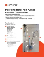
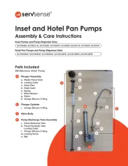
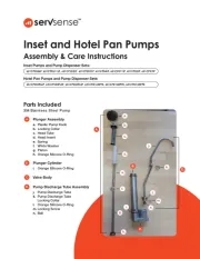
Inset and Hotel Pan Pumps
Assembly & Care Instructions
651CPSSI4LP, 651CPSSI11LP, 651CPSSI2LP, 651CPSSI7LP, 651CPD4IP, 651CPD11IP, 651CPD2IP, 651CPD7IP
651CPSSHPL6P, 651CPSSHPL3P, 651CPSSHPL4P, 651CPD16HPPK, 651CPD13HPPK, 651CPD14HPPK
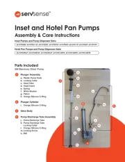
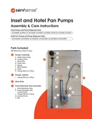
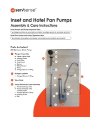
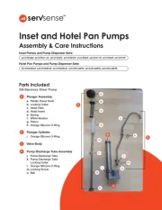
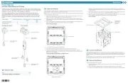
Parts Included
304 Stainless Steel Pump
Inset Pumps and Pump Dispenser Sets:
Hotel Pan Pumps and Pump Dispenser Sets:
A
Plunger Assembly
a. Plastic Pump Knob
b. Locking Collar
c. Head Tube
d. Head Insert
e. Spring
f. White Washer
g. Piston
h. Orange Silicone O-Ring
B
Plunger Cylinder
i. Orange Silicone O-Ring
C
Valve Body
D
Pump Discharge Tube Assembly
j. Pump Discharge Tube
k. Pump Discharge Tube
Locking Collar
l. Orange Silicone O-Ring
m. Locking Screw
n. Ball
A.
B.
C.
D.
a.
b.
c.
d.
e.
f.
g.
h.
i.
j.
k.
l.
m.
n.

Assembled Pump Pump Discharge
Tube Unassembled
Pump Discharge
Tube Unassembled
& Plunger Assembly
Removed from
Cylinder
Pump Discharge
Tube Unassembled
& Plunger Fully
Unassembled
Safety
All components must be cleaned before rst use.
Follow local food safety guidelines and regulations to ensure the food product that is being stored
and/or served is at the proper temperatures.
Clean, rinse, sanitize, and dry parts at a minimum of every 24 hours.
Check local sanitation requirements.
NOTE: Pump is not insulated and is not intended to maintain cold temperatures.
Pump Cleaning
Regular cleaning and maintenance of your ServSense™ pump will ensure proper ation and oper
ultimate performance.
1
For pumps that have been in use, ush and rinse all pump parts with hot water by removing
the pump from the body and putting the lower portion of the pump (valve body) into hot water.
Pump the hot water through the pump until all food product has been expelled and only hot
water is expelled.
2
Disassemble plunger assembly, lid, pump discharge tube assembly and pump cylinder and
valve body. Clean all parts with hot water and dishwashing soap. Use exible brush and wire
brush to clean inside the pump discharge tube and pump cylinder.
3
Rinse completely with warm, clean water.
4
Sanitize all parts according to local sanitation requirements.
5
Air dry parts completely before assembling for use.

Disassembly
1
Remove the pump discharge tube assembly (D) by using a at head screwdriver to
loosen and remove screw (m). Set aside screw and pull on pump discharge tube to release
from valve body (C).
2
Remove the pump plunger assembly (A) by twisting the locking collar counterclockwise to
loosen. Lift plunger assembly (A) out of plunger cylinder (B).
3
Pull down on head tube (c) and unscrew pump knob (a) counterclockwise to remove.
4
Lift o locking collar (b), head tube (c), head insert (d), spring (e) and white washer (f) from
piston (g). Remove orange silicone o-ring (h) from base of piston.
5
Twist plunger cylinder (B) counterclockwise to remove from valve body (C).
6
Remove orange o-ring (i) from base of pump cylinder (B)
Assembly
Plunger Cylinder into Valve Body
1
Replace o-ring (i) onto base of plunger cylinder (B). Screw plunger cylinder (B) into Valve body
(C) clockwise until tight.
Plunger Assembly
2
Insert orange o-ring (h) onto base of piston (g).
3
4
5
Slide white washer (f) back onto piston (g). Slide spring (e) onto piston (g) next.
Slide plastic head insert (d) onto spring (e), followed by head tube (c) and locking collar (b).
Press down onto head tube (c) to expose top screw on piston (g). Screw silver plastic pump
knob (a) onto piston screw by turning clockwise until tight.
Pump Discharge Tube Assembly
6
7
8
Replace orange o-ring (l) onto base of pump discharge tube (j).
Add ball (n) back into valve body (C).
Insert pump discharge tube (j) into Valve body (C). Ensure the hole on the tube (j) and valve
body (C) line up. Use a at head screwdriver to tighten screw (m) back onto valve body (C).
Final Assembly with Lid
9
10
Add lid to pump by threading the pump discharge tube (j) through smaller hole on lid and
inserting plunger cylinder (B) through larger hole on the lid.
Add plunger assembly (A) into hole on plunger cylinder (B) and tighten locking collar (b) to
complete assembly.
Product specificaties
| Merk: | ServSense |
| Categorie: | Niet gecategoriseerd |
| Model: | 651CPSSI11LP |
Heb je hulp nodig?
Als je hulp nodig hebt met ServSense 651CPSSI11LP stel dan hieronder een vraag en andere gebruikers zullen je antwoorden
Handleiding Niet gecategoriseerd ServSense
10 Juni 2025
10 Juni 2025
10 Juni 2025
10 Juni 2025
10 Juni 2025
10 Juni 2025
10 Juni 2025
9 Juni 2025
9 Juni 2025
Handleiding Niet gecategoriseerd
- Klavis
- Navman
- Car Jack
- Testec
- Potenza
- Leen Bakker
- Ferplast
- Kuryakyn
- Dangerous Music
- Baseus
- Vogels
- Extron
- Lenovo
- Minn Kota
- 3B
Nieuwste handleidingen voor Niet gecategoriseerd

10 September 2025
Epson WorkForce Feed Roller Assembly Kit B12B813561 Handleiding
9 September 2025
9 September 2025
9 September 2025

9 September 2025

9 September 2025
9 September 2025

9 September 2025
9 September 2025

9 September 2025