Scanstrut Flip Pro Duo SC-MULTI-F2 Handleiding
Scanstrut Niet gecategoriseerd Flip Pro Duo SC-MULTI-F2
Bekijk gratis de handleiding van Scanstrut Flip Pro Duo SC-MULTI-F2 (11 pagina’s), behorend tot de categorie Niet gecategoriseerd. Deze gids werd als nuttig beoordeeld door 65 mensen en kreeg gemiddeld 5.0 sterren uit 6 reviews. Heb je een vraag over Scanstrut Flip Pro Duo SC-MULTI-F2 of wil je andere gebruikers van dit product iets vragen? Stel een vraag
Pagina 1/11
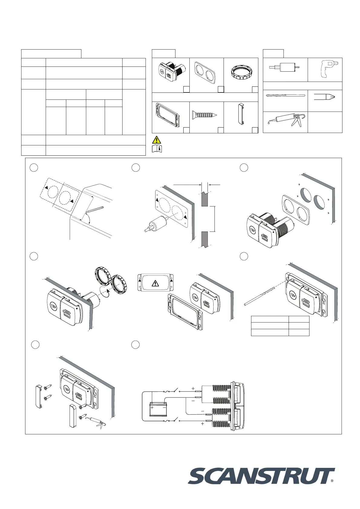
FLIP PRO DUO USB-A & USB-C WITH 12V POWER SOCKET
(SC-MULTI-F2)
04-10-2023 (Issue 1)
Installation Instructions
For further installation
and warranty information
please visit:
www.scanstrut.com
USA
+1 860 308 1416
UK & International
+44 (0)1392531280
Draw a centre line to align template,
ensure line is square on surface and
correct orientation.
90°
TOP
1
Use drilling template to drill x2 Ø32mm
(1 1/4”) holes (see tools required).
Ø32mm
(1.25”)
3mm (0.11”) Min
25mm (1”) Max
2
Feed barrels through the gasket and
holes.
3
4
6
7
REAR INSTALL ONLY
Tighten lock rings onto product until
secure.
FRONT INSTALL ONLY
Push bezel onto the product, make sure the
bezel orientation is correct.
FRONT INSTALL ONLY
Apply silicone seal on xings and pilot
holes.
Connect to 12V supply, ensuring a waterproof
connection. Fuse and select cable diameter
according to input voltage and current for your
specic installation.
** If using a 24V system a voltage converter is
required on the 12V socket only**
Pilot Hole Size
Material No. 6 Screw
Soft Material e.g Plywood2.5mm (3/32”)
Hard Material e.g Fiberglass3mm (1/8”)
FRONT INSTALL ONLY
Drill 4 pilot holes for bezel.
5
TOP
32mm (1 1/4”) Hole sawDrill
Front install only
Drill bit 2.5mm (3/32”) or
3mm (1/8”)Pozi screwdriver
Silicone
Tool list:
12V Socket & USB
chargerGasketLock ring
Front install only
Front t bezel
No.6x20mm
screwsScrew cover
Parts list:
x1
x1
x1
x4
x2
x2
For latest tech info visit: www.scanstrut.com/USB
READ IMPORTANT SAFETY INFORMATION BEFORE INSTALLING.
Technical information:
USB Charger12V Socket
Input
voltage
12/24V system
10-32V DC
12V system
10-15V DC
Input
current max
6A10A
Output type
(12V system) (24V system)
12V⎓10A
USB-A USB-CUSB-AUSB-C
5V⎓3A,
9V⎓3A,
12V⎓3A
MAX
5V⎓3A,
9V⎓3A,
12V⎓3A
MAX
5V⎓3A,
9V⎓3A,
12V⎓3A
MAX
5V⎓3A,
9V⎓3A,
12V⎓3A
15V⎓3A,
20V⎓3A
MAX
Standby
draw
< 0.1W
Waterproof
rating
IPX4 front only lid closed
FLIP PRO DUO USB-A
&
USB-C WITH 2V POWER SOCKET
(SC-MULTI-F2)
Installation Instructions
Technical information:
w
'�
E�
E
N
N
.
Q
+
SR
Product specificaties
| Merk: | Scanstrut |
| Categorie: | Niet gecategoriseerd |
| Model: | Flip Pro Duo SC-MULTI-F2 |
Heb je hulp nodig?
Als je hulp nodig hebt met Scanstrut Flip Pro Duo SC-MULTI-F2 stel dan hieronder een vraag en andere gebruikers zullen je antwoorden
Handleiding Niet gecategoriseerd Scanstrut

27 Augustus 2025
27 Augustus 2025
26 Augustus 2025
26 Augustus 2025
26 Augustus 2025
26 Augustus 2025
26 Augustus 2025
25 Augustus 2025
5 Augustus 2025
4 Augustus 2025
Handleiding Niet gecategoriseerd
Nieuwste handleidingen voor Niet gecategoriseerd
21 Mei 2026
21 Mei 2026
21 Mei 2026
21 Mei 2026
21 Mei 2026
21 Mei 2026
21 Mei 2026
21 Mei 2026
21 Mei 2026
21 Mei 2026