Satco S11871 Handleiding
Satco Niet gecategoriseerd S11871
Bekijk gratis de handleiding van Satco S11871 (2 pagina’s), behorend tot de categorie Niet gecategoriseerd. Deze gids werd als nuttig beoordeeld door 2 mensen en kreeg gemiddeld 4.5 sterren uit 2 reviews. Heb je een vraag over Satco S11871 of wil je andere gebruikers van dit product iets vragen? Stel een vraag
Pagina 1/2
WARNING: Risk of Fire or Electric Shock
• Disconnect power before installation or any maintenance of the xture.
• To avoid damage, falling, electric shock or re, do not modify the xture or replace
accessories without conrming with the supplier rst.
• Only authorized, qualied personnel should install this xture and should follow
the owner’s manual.
• Do not dismantle the xture without the supplier’s authorization.
• Do not touch the power supply when the xture is operating.
• For use in environments where an accumulation of non-conductive dust on the
xture may be expected.
• Suitable for indoor/outdoor installations.
IMPORTANT:This product must be installed in accordance with the applicable
installation code by a person familiar with the construction and operation of the
product and the hazards involved.
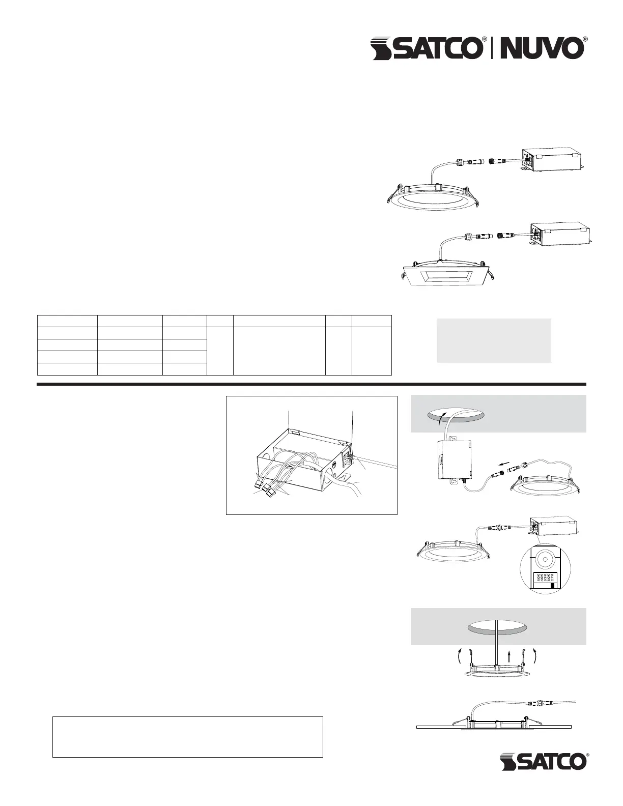
LED CCT SELECTABLE REMOTE
DRIVER DOWNLIGHTS
Models: S11870R1, S11871R1, S11872R1, S11873R1
Satco Products, Inc.
Brentwood, NY 11717
INSTALLATION
INSTALLATION AND SAFETY INSTRUCTIONS
IMPORTANT: Read before installing xture. Retain for future reference.
© Copyright 2025 Satco Products, Inc. 2/25 v1.0
ModelDescriptionWatts VoltsCCTCRIFinish
S11870R14" Round10W
120V
2700K, 3000K, 3500K,
4000K, 5000K
90White
S11871R14" Square9W
S11872R16" Round13W
S11873R16" Square12W
Fixture Includes:
1 LED Lamp
1 Junction Box
TOOLS REQUIRED: Hole saw, measuring
tape and connector cables (as needed).
NOTE: Use extensions if necessary.
Available connector cables are 6' (1.8m).
Connector cables are linkable.
1. Turn power OFF from the electrical panel
before starting installation.
2. Cut a hole in the ceiling for the downlight
in a suitable position. Refer to Hole Cut
Dimensions chart (below).
3. Run the electrical wire from the switch
(power supply wire) through the mounting hole. Use NMD90 Romex or BX cable.
See Figure A.
4. Open the Junction Box swing cover and remove the appropriate knockouts.
5. Insert the power supply wire through the knockout and fasten with a cable connector
(not included).
6. Connect wires inside the Junction Box using the quick connect terminals. Connect
green ground with the green box wire. Connect the black and white power leads with the
matching black and white box wires. See Wiring Diagram.
7. Put all wires and connections back into the box and close the cover securely.
8. New Construction Applications: Junction Box shall be firmly secured to the studs,
joists or similar fixed structural units.
Remodel Applications: Do not require the Junction Box to be firmly secured to xed
structural units.
9. Choose desired color temperature. See Figure B.
10. Bend back the two torsion springs and slowly t the xture through the ceiling hole.
The torsion springs will pull the xture into place. See Figures C & D.
11. Once installation is complete, turn power ON to conrm the xture is working properly.
Hole Cut Dimensions:
4" Round: ø110mm (4.25") 6" Round: ø160mm (6.30")
4" Square: ø110mm (4.25") 6" Square: ø160mm (6.30")
WIRING DIAGRAM
Cable to fixture
Power supply
Green wires
White wires
Black
wires
Quick connect
terminals
Figure A
Figure B
Figure C
Figure D
Meets requirements of ICES-005 issue 5 class A for use in residential applications.
This device complies with part 15 of the FCC Rules. Operation is subject to the following two
conditions: (1) this device may not cause harmful interference, and (2) this device must accept
any interference received, including interference that may cause undesired operation.
Product specificaties
| Merk: | Satco |
| Categorie: | Niet gecategoriseerd |
| Model: | S11871 |
Heb je hulp nodig?
Als je hulp nodig hebt met Satco S11871 stel dan hieronder een vraag en andere gebruikers zullen je antwoorden
Handleiding Niet gecategoriseerd Satco

1 April 2026
1 April 2026
1 April 2026
1 April 2026
1 April 2026
1 April 2026
1 April 2026
1 April 2026
31 Maart 2026
31 Maart 2026
Handleiding Niet gecategoriseerd
Nieuwste handleidingen voor Niet gecategoriseerd
1 April 2026
1 April 2026
1 April 2026
1 April 2026
1 April 2026
1 April 2026
1 April 2026
1 April 2026
1 April 2026
1 April 2026