Samsung AC180JNHFKH Handleiding
Bekijk gratis de handleiding van Samsung AC180JNHFKH (98 pagina’s), behorend tot de categorie Airco. Deze gids werd als nuttig beoordeeld door 99 mensen en kreeg gemiddeld 3.7 sterren uit 50 reviews. Heb je een vraag over Samsung AC180JNHFKH of wil je andere gebruikers van dit product iets vragen? Stel een vraag
Pagina 1/98

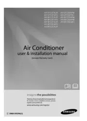
AIR CONDITIONER CONTENTS
SYSTEM AIR CONDITIONER
1. Precautions
2. Product Speci cations
3. Disassembly and Reassembly
4. Troubleshooting
5. PCB Diagram
6. Wiring Diagram
7. Reference Sheet
AC160JNHFKH
AC180JNHFKH
AC200JNHFKH
AC180JNHPKH
AC200JNHPKH
Indoor Unit Outdoor Unit
Model Name
:
AC160JNHFKH AC160JXAFKH
AC160JNHFKH AC160JXAFNH
AC180JNHFKH AC180JXAFNH
AC200JNHFKH AC200JXAFNH
AC180JNHPKH AC180JXAPNH
AC200JNHPKH AC200JXAPNH
Model Code
:
AC160JNHFKH/SA AC160JXAFKH/SA
AC160JNHFKH/SA AC160JXAFNH/SA
AC180JNHFKH/SA AC180JXAFNH/SA
AC200JNHFKH/SA AC200JXAFNH/SA
AC180JNHPKH/EU AC180JXAPNH/EU
AC200JNHPKH/EU AC200JXAPNH/EU
AC160JXAFKH
AC160JXAFNH
AC180JXAFNH
AC180JXAPNH
AC200JXAFNH
AC200JXAPNH
Downloaded from manuals search enginewww.Manualslib.com

Contents
11. Precautions
..........................................................................................................................................
1-1
1-1 Precautions for the Service
.............................................................................................................
1-1
1-2 Precautions for the Static Electricity and PL
................................................................................
1-1
1-3 Precautions for the Safety
...............................................................................................................
1-1
1-4 Others
..................................................................................................................................................
1-1
12. Product Specifications
..................................................................................................................
2-1
2-1 The Feature of Product
....................................................................................................................
2-1
2-2 Product Specifications
.....................................................................................................................
2-2
2-3 Accessory
...........................................................................................................................................
2-8
3. Disassembly and Reassembly
...................................................................................................
3-1
3-1 Indoor Unit
.........................................................................................................................................
3-2
3-2 Outdoor Unit
.....................................................................................................................................
3-14
4. Trouble shooting
..............................................................................................................................
4-1
4-1 Indoor Display Error and Check Method
.....................................................................................
4-1
4-1-1 Indoor unit LED lamp display at error detecting
.............................................................
4-1
4-2 Outdoor Trouble shooting
.............................................................................................................
4-4
4-3 Troubleshooting by symptoms
......................................................................................................
4-6
4-3-1 Indoor temperature sensor (open/short) 4-6 ....................................................................................
4-3-2 Eva in and out sensor (open/short) 4-7 ...............................................................................................
4-3-3 Float switch(Open) 4-8 ................................................................................................................................
4-3-4 Fan error 4-9 ....................................................................................................................................................
4-3-5 EEPROM error 4-10 ..........................................................................................................................................
4-3-6 Option error 4-11 .............................................................................................................................................
4-3-7 Terminal Block's Terminal Fuse(Open) 4-12 ..........................................................................................
4-3-8 Communication error after finishing tracking (E202) 4-13 ............................................................
4-3-9 Outdoor's service valve(Clog) 4-14 ..........................................................................................................
4-3-10 No Power(completely dead) - Initial diagnosis 4-15 ......................................................................
4-3-11 E102 : Communication error between indoor and outdoor unit
E201 : Unit quantity miss matching beween Indoor and Outdoor
E202 : Abnormal state, no communication between Indoor and Outdoor Main PCB
E203 : 1min Time out of communication error(Main 4-19Inverter) ......................................
4-3-12 External Sensor Error (Error Code: E221, E231, E251, E320) 4-20 ..............................................
4-3-13 E403 : Freezing control causes comp. down 4-21 ...........................................................................
4-3-14 E416 : Dischage temperature sensor error 4-22 ...............................................................................
4-3-15 E440, E441 : Abnormal outside temperature halts operation of the compressor 4-23 ...
4-3-16 Outdoor unit BLDC Fan1 or Fan2 error (E458 : Fan1 error, E475 : Fan2 error) 4-24 ...........
4-3-17 E461: Compressor start error
E467: Compressor wire missing error 4-25 ........................................................................................
4-3-18 E462 : Current protection control causes comp. down
E484 : PFC overload errorr 4-26 ..............................................................................................................
4-3-19 E463 : OLP protection control caused comp. down 4-27 .............................................................
4-3-20 E464 : O.C. (Over Current) error 4-28 .....................................................................................................
4-3-21 E466: DC Link Over voltage/ Low voltage error 4-29 .....................................................................
4-3-22 Pipe Blocking Error (Error Code: E422) 4-30 .......................................................................................
Downloaded from manuals search enginewww.Manualslib.com

Contents
4-3-23 The others 4-31 ..............................................................................................................................................
4-4 Setting Option Setup Method ...................................................................................................................... 4-32
4-5 Items to be checked first ................................................................................................................................ 4-38
5. PCB Diagram and Parts list
..........................................................................................................
5-1
5-1 INDOOR UNIT 5-1 .....................................................................................................................
5-2 OUTDOOR UNIT 5-4 ................................................................................................................
6. Wiring Diagram
.................................................................................................................................
6-1
6-1 Indoor Unit 6-1 ............................................................................................................................................................
6-2 Outdoor Unit 6-2 ........................................................................................................................................................
7. Reference Sheet
...............................................................................................................................
7-1
7-1 Refrigerating Cycle Diagram
..........................................................................................................
7-1
7-2 Index for Model Name
.....................................................................................................................
7-2
Downloaded from manuals search enginewww.Manualslib.com
Product specificaties
| Merk: | Samsung |
| Categorie: | Airco |
| Model: | AC180JNHFKH |
Heb je hulp nodig?
Als je hulp nodig hebt met Samsung AC180JNHFKH stel dan hieronder een vraag en andere gebruikers zullen je antwoorden
Handleiding Airco Samsung
3 Augustus 2025

3 Augustus 2025
16 Juli 2025

15 Juli 2025
14 Juli 2025

8 Juli 2025
7 Juli 2025

7 Juli 2025

7 Juli 2025
7 Juli 2025
Handleiding Airco
- Honeywell
- Black Decker
- Point
- House & Luft
- SEEGER
- Ferroli
- Jocca
- Emerson
- Manta
- H.Koenig
- Mistral
- MPM
- Balay
- Equation
- Airwell
Nieuwste handleidingen voor Airco

19 September 2025
19 September 2025
19 September 2025
18 September 2025
18 September 2025
18 September 2025
18 September 2025
18 September 2025

18 September 2025
18 September 2025