Roland V-Drums TD316 Handleiding
Roland Niet gecategoriseerd V-Drums TD316
Bekijk gratis de handleiding van Roland V-Drums TD316 (2 pagina’s), behorend tot de categorie Niet gecategoriseerd. Deze gids werd als nuttig beoordeeld door 16 mensen en kreeg gemiddeld 4.4 sterren uit 7 reviews. Heb je een vraag over Roland V-Drums TD316 of wil je andere gebruikers van dit product iets vragen? Stel een vraag
Pagina 1/2
*5100093003-02*
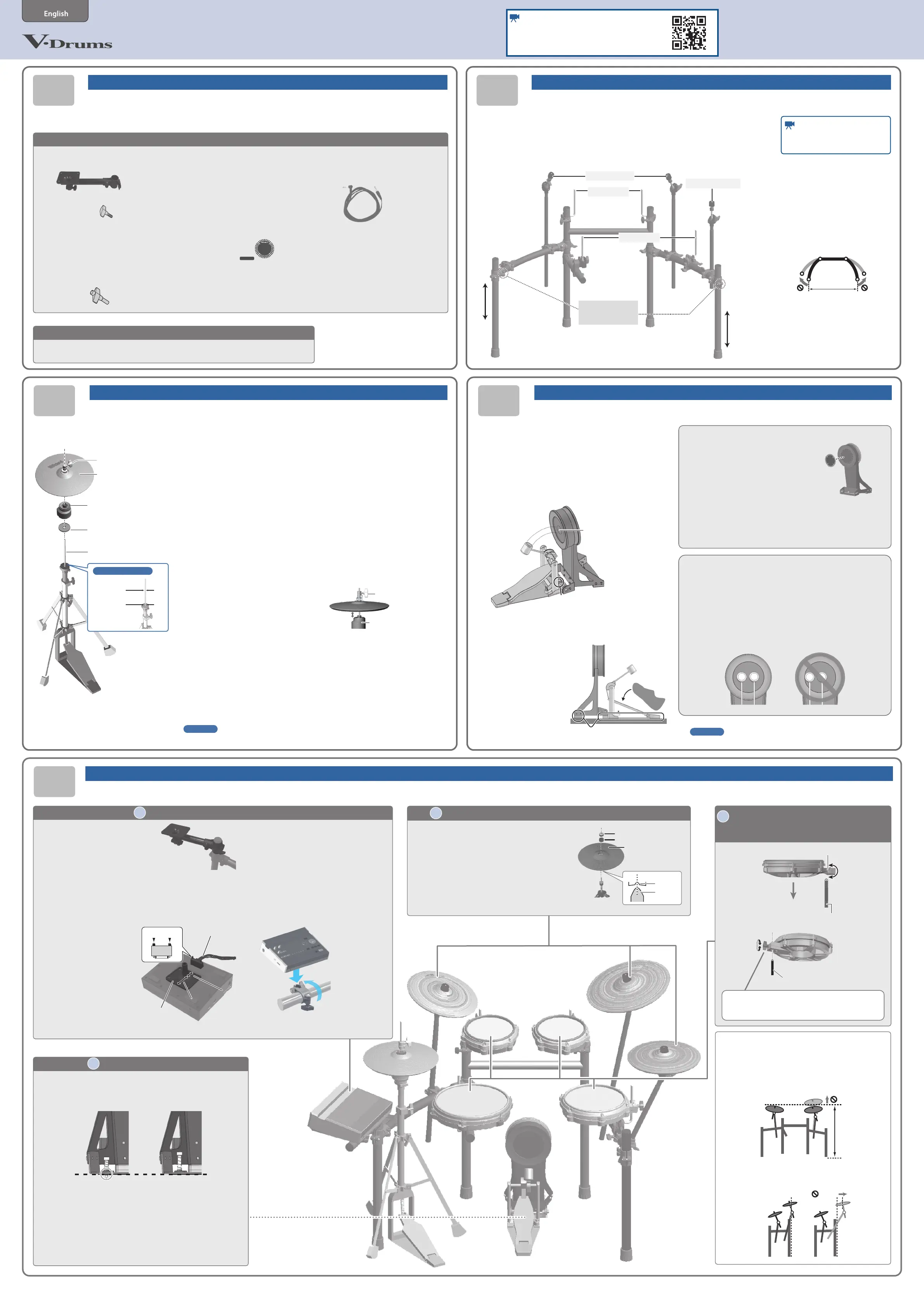
Attach the parts
01010202
0505
03030404
TD316
For details on each component, refer to the respective owner’s manual.
Check the included itemsAssemble the stand
As soon as you open the package, check to see that all items are included. If anything is
missing, please contact your dealer.
* A Phillips screwdriver (#2) is required to assemble this product, available separately.
* This package does not include a kick
pedal, and a hi-hat stand. Use with a
commercially available kick pedal, and a
hi-hat stand.
Assembling the hi-hat (VH-10)Assembling the kick (KD-10)
Assemble the stand (MDS-Compact2) following the procedure described in the owner’s
manual.
* The tip of the mount is sharp. Handle it with care.
* When setting up or storing the stand, be careful not to pinch the ngers you use to
handle the stand.
* Make sure that the four vertical stand pipes are standing upright.
MDS-Compact2
* For the items included with the stand (MDS-Compact2), refer to the owner’s manual when
checking that all items are included.
Cymbal mountsCymbal mounts
Cymbal mountCymbal mount
Pad mountsPad mounts
Pad mountsPad mounts
If the stand wobbles, If the stand wobbles,
loosen this hand knob loosen this hand knob
and adjust the height.and adjust the height.
¹V31 (Drum sound module) x 1
–Sound module mounting plate set x 1
¹PD-12P (V-Pad for snare) x 1
–Knob bolt x 1
¹PD-8H (V-Pad for tom 1, 2) x 2
¹PD-10H (V-Pad for tom 3) x 1
¹VH-10 (V-Hi-hat) x 1
¹CY-12C-T (V-Cymbal for crash 1, 2) x 2
¹CY-14R-T (V-Cymbal for ride) x 1
¹KD-10 (kick pad) × 1
¹Drum Key × 1
Owner’s Manual
¹TD316 Setup Guide (this document)
¹V31 Quick Start
–Roland Cloud Connect Setup Guide
¹PD-12P/PD-10P Owner’s Manual
¹PD-10H/PD-8H Owner’s Manual
¹VH-10 Owner’s Manual
¹CY-14R-T/CY-12C-T Owner’s Manual
¹KD-10 Owner’s Manual
–Kick drum patch
–Anti-slip sheet
–Leaet Note (Using anti-slip sheet)
Cables
¹Dedicated connection cable x 1
(included with V31)
¹Trigger cable x 1
* The V31 and PD-12P accessories
are in the respective packing
cartons.
* The drum key is located in the
plastic bag that contains the
Owner’s Manual.
* The trigger cable is located in
the plastic bag that contains the
Owner’s Manual.
Time requiredTime required: approx. : approx.
2020
min. min.
Time requiredTime required: approx. : approx.
4040
min. min.
Time requiredTime required: approx. : approx.
3030
min. min.
Time requiredTime required: approx. : approx.
22
min. min.Time requiredTime required: approx. : approx.
33
min. min.
1. Remove the clutch included with
the hi-hat stand (commercially
available) from the cymbal rod.
* The clutch included with the hi-hat
stand will not be used.
* It is not necessary to remove the felt
component (or rubber portion) on the hi-
hat stand used for supporting the bottom
cymbal.
2. Conrm that the cymbal rod is
rmly secured.
For instructions on tightening the cymbal
rod, refer to the owner’s manual for your
cymbal stand.
* Looseness or play in the cymbal rod can
make the top hi-hat unstable, causing
it to shake or turn, and prevent proper
functioning.
3. With the sponge surface of
the anti-vibration plate facing
upward, pass it over the cymbal
rod.
This will rest on top of the felt component
(or rubber portion) of the hi-hat stand’s
cymbal receiver.
4. Place the motion sensor unit
with the cymbal rod passing
through the hole of the motion
sensor unit.
* Position the CONTROL OUT jack on the
farther side, as viewed from the player.
5. Pass the hi-hat over the cymbal
rod.
Positioning the “Roland” logo on the
farther side, as viewed from the player will
provide the best sensitivity.
6. With the hi-hat completely
separated from the motion
sensor unit, tighten the clutch
screw.
motion sensor unitmotion sensor unit
SeparatedSeparated
clutch screwclutch screw
* When turning the VH-10 upside down,
protect the clutch and the sensor from
damage. Handle the unit with care so that
it is not dropped or overturned.
Clutch screwClutch screw
Hi-hatHi-hat
Motion sensor unitMotion sensor unit
* CONTROL OUT jack on the farther
side, as viewed from the player
* “Roland” logo on the farther
side, as viewed from the
player
* Sponge side up
Insulating plateInsulating plate
Cymbal rodCymbal rod
Diameter: 6.0–7.0 mmDiameter: 6.0–7.0 mm
Diameter: 11.7 mm Diameter: 11.7 mm
Max.Max.
Compatible stands
1. Follow the instructions in the “Leaet Note” (Using
anti-slip sheet) that’s included with this product to
apply the anti-slip sheet.
2. Attach the kick pedal (commercially available) to
the KD-10.
Position the beater so that it strikes the center of the head, then
secure the kick pedal and KD-10 rmly in place.
* Take care not to pinch your ngers.
BeaterBeater
Install the kick pedal Install the kick pedal
securely.securely.
Beater must hit the center Beater must hit the center
of the striking surfaceof the striking surface
3. Step on the kick pedal and make sure that it’s
properly attached and in a stable position.
Check to make sure that the
KD-10 and the kick pedal
both make contact with the
oor.
Check to be sure they’re making contact Check to be sure they’re making contact
with the oorwith the oor
Reference
For details on the kick, refer to “KD-10 Owner’s Manual”.
Reference
For details on the hi-hat, refer to “VH-10 Owner’s Manual”.
Using a felt beater
1. To protect the batter head pad face,
be sure to apply the included kick
drum patch to the pad face.
When using a non-felt beater, you can keep
using the pad normally with the patch still on.
* If you wish to remove the marks (adhesive) that remain after you peel
o the patch, wipe them o with a cloth and rubbing alcohol.
* Do not use rubbing alcohol on any other parts besides the batter
head pad face. Using rubbing alcohol on plastic or wooden parts
may cause discoloration or damage.
Assembly and connections
Time required: approx.
105
min.
* For reasons of safety, do not spread the
stand wider than 1.2 meters.
When using a twin pedal
Position the two beaters equally apart from the center of the pad as
shown in the gure at left. If one of the beater is further away from the
center than the other, the sound from the further beater will be lower in
volume, or will not sound as desired.
If you’re using twin pedals, the sensitivity will be lower than when a
single pedal is used. Raise the sensitivity on the sound module.
For details, refer to the V31’s owner’s manual.
Correct positioningCorrect positioningIncorrect positioningIncorrect positioning
22
Attach the snare (PD-12P) and toms
(PD-8H/PD-10H)
LoosenLoosen
TightenTighten
Diameter of mountable rods: 9–13 mmDiameter of mountable rods: 9–13 mm
Knob bolt (included)Knob bolt (included)
CY-12C-TCY-12C-T
PD-12PPD-12P
PD-8HPD-8HPD-8HPD-8H
PD-10HPD-10H
CY-14R-TCY-14R-T
CY-12C-TCY-12C-T
KD-10KD-10
VH-10VH-10
V31V31
11
Installing the kick (KD-10)
If you’re using this unit on a V-Drums mat, on a Noise Eater (NE-10), or on
carpet, extending the anchor bolts will secure the unit in place, making it
easier for you to perform.
* When used on ooring, the anchor bolts may damage the oor.
* The tips of the anchor bolts are sharp. Handle with care.
When using on When using on
the V-Drums mat,the V-Drums mat,
Noise Eater, or carpetNoise Eater, or carpet
When using on When using on
the oorthe oor
44
Attaching the drum sound module (V31)
1. Attach the sound module
mounting plate that’s included
with the drum sound module
to the stand.
2. Remove the sound module mounting plate from the
sound module mounting plate set.
3. Flip the drum sound module over.
* When turning the unit over, be careful so as to protect the buttons
and knobs from damage.
4. Remove the screws on
the bottom of the drum
sound module, and
attach the sound module
mounting plate to the
drum sound module.
Wide partWide part
Narrow partNarrow part
Sound module mounting plateSound module mounting plate
Connection cable
Knob
5. Attach the connection cable that’s
included with the drum sound
module to the drum sound module
(bottom side).
Insert the connector all the way, then turn the
knobs to fasten them securely.
6. Rotate the mount holder as shown
in the illustration, then insert the
sound module mounting plate into
the mount holder to fasten it.
Adjusting the position of the cymbal
* Adjust the cymbal positions as shown below, as it is very
dangerous if the stand falls over.
Adjust the height of the rod so that the highest point of
the cymbal is less than 1.2 meters.
Attach the cymbal so that its center does not extend toward the
back beyond the pipes of the stand (the pipes at the back of the
stand).
33
Attach the crash cymbal (CY-12C-T) and ride cymbal (CY-14R-T)
1. Position the cymbal so that the convex
portion of the cymbal mount is aligned
with the concave portion of the bottom
of the cymbal.
2. Tighten the cymbal nut to obtain an
appropriate amount of sway.
* Use the cymbal nut and felt washer that are
included with the drum stand.
“Roland” logo on the
farther side, as viewed
from the player
Cymbal nut
Felt washer
convex convex
portionportion
concave concave
portionportion
LoosenLoosen
TightenTighten
Diameter of mountable rods: 8–13 mm
Watch the video manual
See the following video manual for how to assemble
this product.
https://roland.cm/td316qs
* Before attaching the parts, make sure that the four vertical stand pipes are standing upright.
Install the included knob bolt onto the PD-12P before
mounting the pad onto the stand.
OKOK
TD316 Setup GuideTD316 Setup Guide
Watch the video manual
Also, watch the video manual for how
to assemble this stand.
1.2 m1.2 m
1.2 m1.2 m
Product specificaties
| Merk: | Roland |
| Categorie: | Niet gecategoriseerd |
| Model: | V-Drums TD316 |
Heb je hulp nodig?
Als je hulp nodig hebt met Roland V-Drums TD316 stel dan hieronder een vraag en andere gebruikers zullen je antwoorden
Handleiding Niet gecategoriseerd Roland

21 Juni 2026
15 Mei 2026
14 Mei 2026
13 Mei 2026
13 Mei 2026
12 Mei 2026
12 Mei 2026
12 Mei 2026
12 Mei 2026
12 Mei 2026
Handleiding Niet gecategoriseerd
Nieuwste handleidingen voor Niet gecategoriseerd
25 Juni 2026
25 Juni 2026
25 Juni 2026
25 Juni 2026
25 Juni 2026
25 Juni 2026
25 Juni 2026
25 Juni 2026
25 Juni 2026
24 Juni 2026