Rikon 70-1516VSR Handleiding
Rikon Niet gecategoriseerd 70-1516VSR
Bekijk gratis de handleiding van Rikon 70-1516VSR (28 pagina’s), behorend tot de categorie Niet gecategoriseerd. Deze gids werd als nuttig beoordeeld door 89 mensen en kreeg gemiddeld 4.0 sterren uit 8 reviews. Heb je een vraag over Rikon 70-1516VSR of wil je andere gebruikers van dit product iets vragen? Stel een vraag
Pagina 1/28
www.rikontools.com
70-1516VSRM1
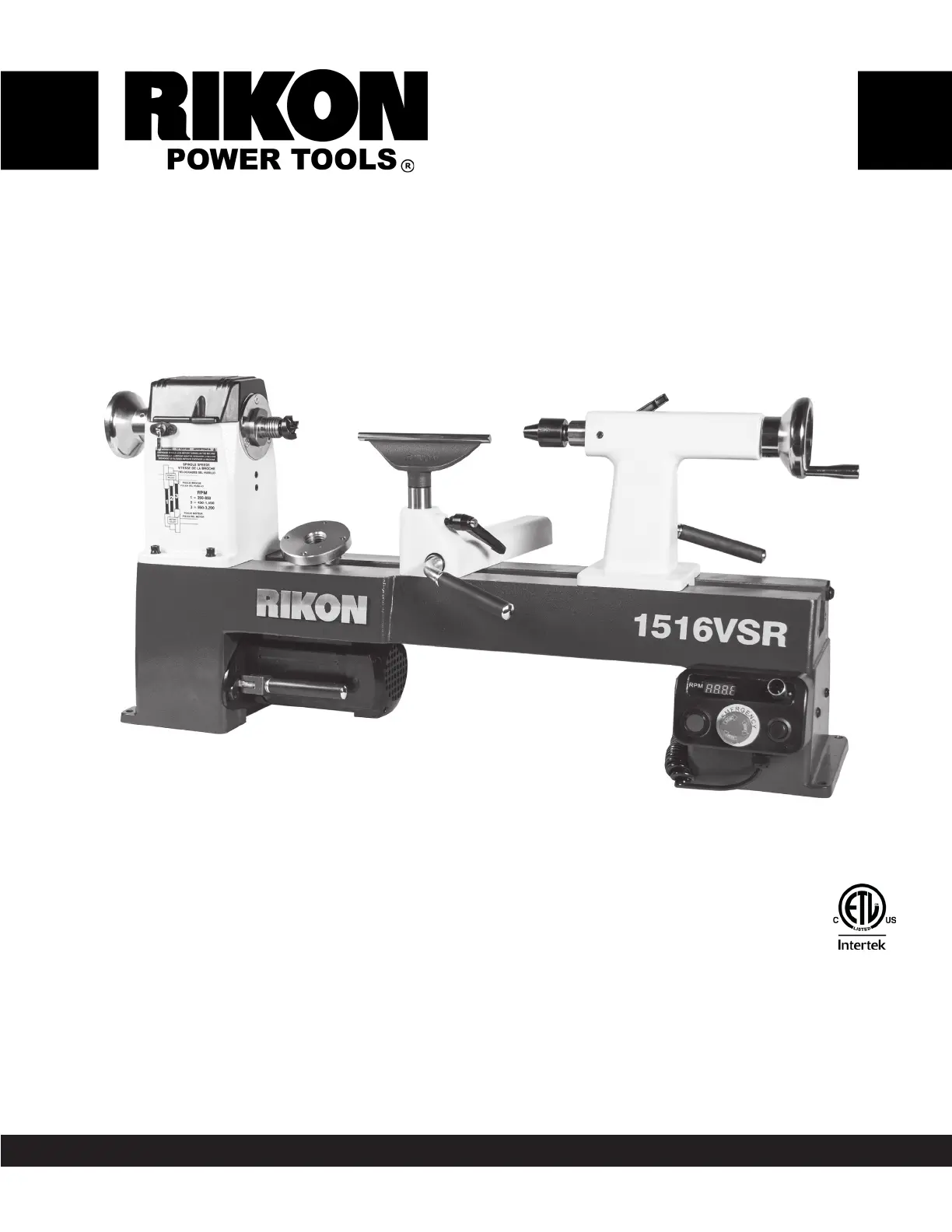
12” x 16-1/2” Midi VSR Lathe
Operator’s Manual
Record the serial number and date of purchase in your manual for future reference.
Serial Number: _________________________ Date of purchase: _________________________
For technical support or parts questions, email [email protected] or call toll free at (877) 884-5167
The serial number can be found on the specication label on the rear of your machine.
70-1516VSR
Product specificaties
| Merk: | Rikon |
| Categorie: | Niet gecategoriseerd |
| Model: | 70-1516VSR |
Heb je hulp nodig?
Als je hulp nodig hebt met Rikon 70-1516VSR stel dan hieronder een vraag en andere gebruikers zullen je antwoorden
Handleiding Niet gecategoriseerd Rikon

5 Maart 2026
14 Augustus 2025
10 Maart 2025
3 Maart 2025
4 December 2024
3 Oktober 2024
3 Oktober 2024
2 Oktober 2024
2 Oktober 2024
5 Augustus 2024
Handleiding Niet gecategoriseerd
Nieuwste handleidingen voor Niet gecategoriseerd
9 Maart 2026
9 Maart 2026
9 Maart 2026
9 Maart 2026
9 Maart 2026
9 Maart 2026
9 Maart 2026
9 Maart 2026
9 Maart 2026
9 Maart 2026