RIDGID 65R-C Handleiding
RIDGID Niet gecategoriseerd 65R-C
Bekijk gratis de handleiding van RIDGID 65R-C (108 pagina’s), behorend tot de categorie Niet gecategoriseerd. Deze gids werd als nuttig beoordeeld door 89 mensen en kreeg gemiddeld 4.1 sterren uit 5 reviews. Heb je een vraag over RIDGID 65R-C of wil je andere gebruikers van dit product iets vragen? Stel een vraag
Pagina 1/108
Threading
1.Inspect the threader before use. Replace dies or any
other part that shows damage or wear. To insure high
thread quality, only use RIDGID replacement dies.
Worn dies can result in poor thread quality
and high handle forces.
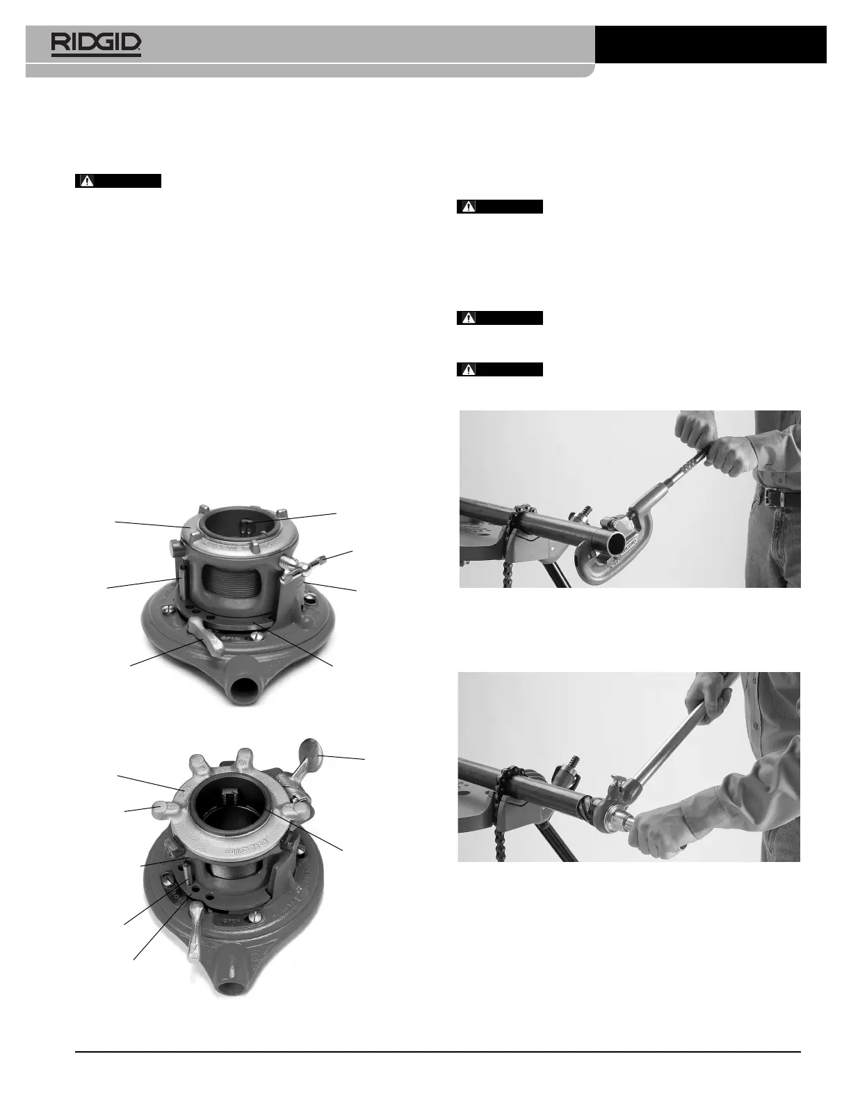
2.Mount the pipe firmly in a pipe vise. When threading an
existing pipe, make sure it is secure and will not move.
Cut the end of the pipe cleanly and squarely using a
pipe cutter
(Figure 3)
.
To prevent tipping, long lengths of pipe
should also be supported with a pipe stand. Vise and
stands should be on level ground.
When working on a scaffold or lift, the oper-
ator should be properly secured to prevent injury in the
event of a fall.
Figure 3 – Cutting End Of Pipe
3.Ream the end of the pipe to remove any burrs that may
have been produced during the cutting of the pipe
(Figure 4)
.
Figure 4 – Reaming End Of Pipe
4.Adjust thread size for the size pipe to be threaded (refer
to previous instructions for thread size adjustment).
5.Adjust workholder:
65R-C:Turn gauge ring until desired pipe size corresponds
with mark on top of workholder
(Figure 1)
.
65R-TC:Turn gauge ring until desired pipe size is aligned
with locking cam
(Figure 2)
.
RIDGID
®
5/14
Printed in U.S.A.
EC40741
999-998-280.10
REV. C
RIDGID
®
65R-C and 65R-TC Threaders are designed to
thread 1" to 2" pipe and conduit using a manually operated
internal ratchet.
Read these instructions carefully before
using this tool. Failure to follow all instructions may
result in property damage and/or serious injury.
Thread Size Adjustment
1.Place threader with workholder up
(Figures 1 and 2)
and unscrew workholder by turning counter-clockwise
until change plate is clear of posts.
2.Move post to desired pipe size. Screw workholder
clock wise until change plate slides over post.
3.Adjust change plate to desired thread size.
Standard Size Thread:Set change plate between the two
“Standard” marks.
Oversize Thread:For oversize (shallow) thread, set change
plate slightly below the “Standard” marks.
Undersize Thread:For undersize (deep) thread, set change
plate slightly above the “Standard” marks.
Figure 1 – 65R-C Threader
Figure 2 – 65R-TC Threader
65R-C & 65R-TC Manual Pipe Threader Instructions
WARNING
Gauge
Ring
Post
Change
Plate
Workholder
Jaw
Clamp
Screw
Standard
Marks
Release Cam
Lever
Gauge
Ring
Workholder
Jaw
Locking
Cam
Change
Plate
Lugs
Post
Workholder
WARNING
WARNING
WARNING
Product specificaties
| Merk: | RIDGID |
| Categorie: | Niet gecategoriseerd |
| Model: | 65R-C |
Heb je hulp nodig?
Als je hulp nodig hebt met RIDGID 65R-C stel dan hieronder een vraag en andere gebruikers zullen je antwoorden
Handleiding Niet gecategoriseerd RIDGID

6 December 2025
27 November 2025
27 November 2025
26 November 2025
25 November 2025
25 November 2025
24 November 2025
24 November 2025
24 November 2025
26 Augustus 2025
Handleiding Niet gecategoriseerd
Nieuwste handleidingen voor Niet gecategoriseerd
23 Juli 2026
23 Juli 2026
23 Juli 2026
23 Juli 2026
23 Juli 2026
23 Juli 2026
22 Juli 2026
22 Juli 2026
22 Juli 2026
22 Juli 2026