Relacart PM-320 Handleiding
Bekijk gratis de handleiding van Relacart PM-320 (2 pagina’s), behorend tot de categorie Microfoon. Deze gids werd als nuttig beoordeeld door 53 mensen en kreeg gemiddeld 5.0 sterren uit 27 reviews. Heb je een vraag over Relacart PM-320 of wil je andere gebruikers van dit product iets vragen? Stel een vraag
Pagina 1/2

2
2
2
2
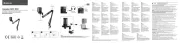
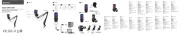
Power switch with indicator light
Function operation knob: turn this knob left and right to select the menu,
press the knob to set the system operation menu.
Headphone monitor jack, stereo output.
“ ” Volume operation button: increase the input volume gain.
“ ” Volume operation button: attenuate the input volume gain.
OLED display: display frequency, frequency group and channel, battery life,
etc.
Infrared data transmission (iR) window: Infrared pairing window, receiving
the data signal transmitted by the receiver.
Infrared data transmission data (SYNC) button: Press this button to transmit
the channel and setting data of the transmitter to the receiver.
( ) .
Antennas A and B.
Power switch/volume potentiometer.
3.5mm stereo headphone monitor jack.
Antenna A indicator: When the battery level shows 1 bar, the antenna indicator
changes from blue to red.
Antenna B indicator: When the battery level shows 1 ba, the antenna indicator
changes from blue to red.
OLED display: display frequency, frequency group channel, battery life, etc.
Anti-pull device, used for power cord.
The 12V connection jack (DC IN) of the external power adapter.
A: 6.3 mm jack, the left side is the audio output (LOOP OUT BAL 1/L) .
B: 6.3 mm jack, the right side is the audio output (LOOP OUT BAL 2/R) .
A: XLR-3/6.3 mm combo jack, on the left is the audio input (BAL AF IN 1/L) .
B: XLR-3/6.3 mm combo jack, on the right is the audio input (BAL AF IN 2/R) .
BNC interface, antenna output interface.
Note: In mono mode, the signal from the left audio input terminal (XLR-3/6.3
mm combo jack, BAL AF IN 1/L) will be sent.
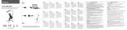
Volume input: Display the set volume input parameters.
Radio frequency display: The device is transmitting radio signals.
Transmit power: set transmit power. ( “ ” High transmit power, “ ”
low transmit power)
Audio mode: When mono is selected, it is displayed as “ ” , Pilot function
is automatically turned off.
When stereo is selected, it is displayed as “ ” , Pilot function
is automatically turned on.
Control sound “P” : Control sound analysis has been enabled. When stereo is
selected, the pilot analysis sound is turned on automatically, and when mono
is selected, the pilot analysis sound is turned off automatically.
“Display Mode” status display: A. Frequency: the set transmitting frequency.
B. Group, channel: set group and channel.
C. Name: set name freely.
Key lock: The key lock is enabled on the transmitter.
Audio frequency: left (AF L) and right (AF R) audio channels, indicating the
level of audio input.
1
1
1
1
3
3
3
3
4
4
5
5
4
4
6
6
7
7
8
5
6
Receiver 1 *
Transmitter 1 *
BNC antenna 1 *
External power adapter 1 *
1 5VAA battery 2. *
Stereo line 2 *
1U Rack mount kit including screws 1 set ( ) *
Simple operation manual 1 *
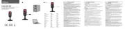
PM-320: Front panel: Rear panel:
1 2 3 4 5 6
System Overview
PM-320 is a wireless monitoring system for stage performances and
audio broadcasting, and a wireless listening system for large simultaneous
interpretation conferences. High-fidelity sound, advanced electronic
processing technology instead of the traditional complicated and heavy
monitoring equipment, eliminate the howling from the monitoring equipment,
and make the performance reliable and perfect.
System performance characteristics
· / Metal 1 2 EIA standard 1U case.
· The housing of PM-320R receiver is made of light-weight and tough alloy
materials.
· Exquisite and simple OLED display.
· The receiver uses the UHF frequency band, and the CPU controls diversity
reception to reduce dead spots and ensure stable reception.
· The bandwidth is 32MHz and there are 1280 adjustable frequencies. 1-10
Channel groups, more than 180 fixed frequencies for choose. Channel
groups U1-U5 can set and save frequencies freely.
· Stereo and mono selection.
· Treble boost function, limit control function.
· The stable PLL phase-locked oscillation circuit, combined with the “noise
lock” squelch can effectively block stray RF.
· With headphone monitoring output.
· With long transmission distance, it is suitable for various occasions.
7 4
8 6 2 135 21 3 4 5
Gr:02 Ch:01
AF
INPUT:-15dB
L AF R
1235
8
7
6
4
8
L
5
7
8
1
2 3
45
6
10
8
9
7
11
12
IR
PM-320 Wireless In ear Monitor System -
UHF Wireless Microphone
Packing list Transmitter function introduction Transmitter display overview Receiver Function Introduction System Introduction
transmits the channel data of the receiver to the transmitter, so that the
frequency of the transmitter and the receiver are consistent.
SET key: enter the menu/or confirm the menu settings.
“ / ” : select function operation keys.
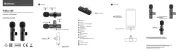
Belt clip: fix the receiver around the waist of the user.
Battery compartment: fill 2 AA batteries. (It is best to use alkaline 1.5V AA
batteries. Please replace two batteries at the same time when replacing
new batteries. )
Warning: Do not install the battery with wrong polarity, which may damage
the internal electronic parts.
Battery cover lock switch: Push this switch to open the battery cover.
Infrared data transmission window (iR) : Infrared frequency window, which
10
11
12
8
9
7

8 9 10 11 12 13 14 15
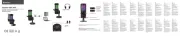
Frequency List: select the fixed frequency in the factory pres et channel
group 1-10 and the freely set frequency from U1 to U 5.
Input L evel: 0 to -42dB, 3dB step.
Mode: s et mono or stereo audio channel.
Display: Display mode. (frequency, group/chanel, name)
Monitor: 0 to 20 levels or mute.
Name: S et a name.
Tools: Enter the bran ch menu.
Tune: Set the channel and transmit frequency of “U1-U5” in the
frequency library.
RF Power: Low or High.
Brightness: Display brig htness. (low, m edium, high)
Version: Display current softwa re version.
Reset: If you reset the transmitter, only the settings of the control
tone and frequency bank “U1-U5” remain unchanged.
Exit: Exit the branc h menu setting and return to the main menu
setti ng.
Transmitter Lock: Turn the transmitter key lock on or off.
RF Mute: Rad io si gnal on or off.
Language: Language selection. (Chin ese or English)
Exit: Exit the operation menu and return to the main interfac e.
Squelch:
Frequency List: select the fixed frequency in the factory preset channel
group 1-10 and the freely set frequency from U1 to U5.
AFS: Scan frequency to select the preset frequency that can be used in
the channel or group.
Balance: Left and right stereo balance settings. (L15 to L1-L=R-R1 to R15)
Mode: set mono/stereo.
High Boost: treble boost.
Limiter: off or -6dB to -18dB, every 6dB step.
Name: Set a name.
RX Lock: Turn the receiver key lock on or off.
Tools:
Display: Display mode. (frequency, group/channel, name)
Tune: Set the receiving frequency of in the frequency
library.
Sync: Synchronized frequency .
Volume Boost: 0 to 6dB, every 3dB step.
Brightness:
Version: Display current software version.
:
:
Language:
:
05 to 35dB, every 5dB step.
Enter the branch menu.
“U1-U5”
Display brightness. (low, medium, high)
Reset If you reset the receiver, only the settings of the control
tone and frequency bank “U1-U5” remain unchanged.
Exit Exit the branch menu setting and return to the main menu
setting.
Language selection. (Chinese or English)
Exit Exit the operation menu and return to the main interface.
PM-320T
Transmitter
PM-320R
Receiver
PM 320R Stereo Mini Receiver PM 320T Stereo Transmitter- -
Receiving method
Carrier frequency band
Maximum deviation
Number of channel groups
Modulation method
S/N ratio
T.H.D.
Stereo separation
Frequency response
Battery
Current consumption
Battery life
High frequency boost
Limiter
Frequency stability
Oscillation mode
Working distance
Output socket
Output power
Sensitivity
Frequency bandwidth
Dimensions
Weight
antenna diversity reception
554MHz~936 MHZ
±48KHz
single channel
FM MPX (stereo)
>100dB
<0.9%@1KHz
≥55dB, at 1KHz
25Hz-15KHz ±3dB
AAx2
165mA (typical)
> 8 hours
+8 dB at 10KHz
each step can be adjusted 6dB, can be turned off
±0.005% (0~50°C)
PLL phase lock frequency synthesis
100 meters in general (open area)
φ3.5mm stereo headphone socket
2x150mW at 1KHz (T.H.D.: 3%)
When the offset is equal to 25KHz, 6dBuV, S/N>60dB
32MHz (1280 transmitting frequencies, tunable in units of 25 KHz)
90mm (height) x 65mm (width) x 23mm (depth)
about 100g
System installation
1. In order to achieve the best operation of the equipment, the height of the
receiver should be higher than 1 meter from the bottom and at least 1
meter from the wall surface.
2. Keep the antenna away from interference sources, such as computer
equipment, digital equipment, televisions and cars, and also away from
large-area metal objects.
3. Install the antenna on the antenna connector on the rear panel, and pull
the antenna to a position at a 45° angle to the vertical.
4 Minimize obstacles as much as possible between the location of the.
receiver and the place where the transmitter is used.
5 When two transmitters are used at the same time, the distance between.
the transmitter and the receiver must be at least 2 meters.
System connection
1. Connect the output end of the DC12V/1000mA DC output power supply to
the transmitter DC power input socket. To prevent the DC plug from
accidentally detaching, first pass the wire through the fixing hole and then
tighten it.
(Note: The input voltage of the AC power adapter must be selected to meet
the power supply specification range of the area of use.)
2. There are two types of audio jacks on the rear panel of the transmitter,
namely Φ6.3mm balanced output socket and XLR-3/6.3 mm combined
balanced input jack.
Use a suitable cable to connect the output of an external device (such as
a mixer or a second PM-320TX) to the XLR-3/6 3 mm combined balanced .
input jack .
Use a suitable cable to connect the input end of an external device (such
as a mixer or a second PM-320TX) to the Φ6.3 mm balanced output jack.
(Note: After the signals of the input jacks BAL AF IN 1/L and BAL AF IN 2/R
are separated, they continue to be transmitted to the output jacks LOOP
OUT BAL 1/L and LOOP OUT BAL 2/R. Therefore, you can only transmit
Use the output jack when the machine is switched on. )
3. Set the appropriate audio input level
The intensity of the audio input signal will be displayed on the AF level
meter on the OLED display panel, and the intensity of the input audio
signal will be adjusted appropriately. Therefore, the input intensity must be
adjusted appropriately to obtain the best signal-to-noise ratio and dynamic
range, and to avoid signal distortion.
4. Headphone connection
Insert the monitor headphone connection plug into the 3.5mm headphone
stereo socket, you can also connect general headphones or connect the
output end to the audio input of other audio equipment.
Note: The headphone output socket is a stereo output. Note that the
connected plug must be a stereo plug. If it is a mono headphone plug, one
side of the output may be short-circuited and the headphone output circuit
on the other side may be burned.
5. Multi-system mixed group connection mode
Some performers need to hear the signal of their own playing instrument
and the mixed instrument. With the help of this device, each performer can
hear this combination” effect or their independent performance effect,
and send a whole band from the mixer Mix the effect to the first transmitter
(PM-320T) BAL AF IN 1/L and BAL AF IN 2/R input terminals, and then
from the LOOP OUT BAL 1/L and LOOP OUT BAL 2/R output terminals,
connect To the BAL AF IN 1/L and BAL AF IN 2/R inputs of a transmitter.
Using this link, you can operate all transmitters, and create a mixer to
listen to each performer through the auxiliary output of the mixer. Send
these different combinations to each performer’s receiver (PM-320R).
“
PM 320R-
IR
PM 320R-
PM 320R-
IR
IR
PM 320T-
PM 320T-
PM 320T-
mixer
2
Squelch Threshold: Displays the set squelch threshold parameters.
Pilot control tone.
Audio mode: When mono is selected, it is displayed as “ ” , Pilot function
is automatically turned off.
When stereo is selected, it is displayed as “ ” , Pilot function
is automatically turned on.
Key lock: Key lock is enabled on the receiver.
Battery status: 4 bars are fully charged, please replace with new ones in time
when there is one bar left.
“Display Mode” status display: A. Frequency: the set transmitting frequency.
B. Group, channel set group and channel.:
C. Name: freely set name.
“AF” audio frequency: indicates the audio input level of the transmitter.
“RF” radio signal level: the strength of the received radio signal.
1
3
4
6
5
7
8
Gr:02 Ch:0 1
AF
SQ:05
RF
1 2 3
7
6
8
45
Receiver display overview Menu System installation and connection System equipment onnection iagramc d Specification
1
2
Main Frame Size
Frequency band
Maximum deviation
Number of channel groups
Modulation method
S/N ratio
T.H.D.
Frequency bandwidth
Comprehensive frequency response
Output power
Current consumption
Power supply mode
Frequency stability
Oscillation mode
Harmonic radiation
Audio output
MPX control tone
Audio input
Dimensions
Weight
1 / 2 EIA standard 1U
554MHz~936 MHz
±50KHz
single channel
FM MPX (stereo)
>100dB
<0.9%@1KHz
32MHz
25Hz-15KHz ±3dB
30mW-50mW
140mA (typical)
DC 12V
±0.005% (-10~50°C)
PLL phase lock frequency synthesis
more than 60dB lower than the main wave
φ6.3mm balanced socket x2
frequency: 19KHz, deviation: ±5KHz
Line level x 2, XLR and φ6.3mm co composite socket
206mm (width) x 44mm (height) x 199mm (depth)
about 955g
Product specificaties
| Merk: | Relacart |
| Categorie: | Microfoon |
| Model: | PM-320 |
Heb je hulp nodig?
Als je hulp nodig hebt met Relacart PM-320 stel dan hieronder een vraag en andere gebruikers zullen je antwoorden
Handleiding Microfoon Relacart

18 November 2024

18 November 2024

18 November 2024

9 Juli 2023

9 Juli 2023

9 Juli 2023

8 Juli 2023

8 Juli 2023

7 Juli 2023

7 Juli 2023
Handleiding Microfoon
- Yamaha
- Joy-it
- Konig
- Hohner
- Solid State Logic
- Williams Sound
- MayBesta
- AIRHUG
- Max
- Ibanez
- Louroe Electronics
- Comica
- Ultimate Support
- Sontronics
- Peavey
Nieuwste handleidingen voor Microfoon
17 September 2025
15 September 2025
15 September 2025
15 September 2025
15 September 2025
15 September 2025
15 September 2025
15 September 2025
15 September 2025
15 September 2025