Panasonic PM2LF10 Handleiding
Panasonic
Niet gecategoriseerd
PM2LF10
Bekijk gratis de handleiding van Panasonic PM2LF10 (1 pagina’s), behorend tot de categorie Niet gecategoriseerd. Deze gids werd als nuttig beoordeeld door 45 mensen en kreeg gemiddeld 3.9 sterren uit 23 reviews. Heb je een vraag over Panasonic PM2LF10 of wil je andere gebruikers van dit product iets vragen? Stel een vraag
Pagina 1/1

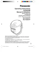
INSTRUCTION MANUAL
CAUTIONS2
●
●
●
●
●
●
●
●
●
●
●
●
This product has been developed / produced for in-
dustrial use only.
A reverse supply protection circuit and output short-
circuit protection circuit are not incorporated. Since
wrong wiring may cause malfunction, make sure to
check the terminal arrangement, cable wiring and
power supply area before wiring.
Make sure that the power supply is o while wiring.
Verify that the supply voltage variation is within the rating.
If power is supplied from a commercial switching reg-
ulator, ensure that the frame ground (F.G.) terminal of
the power supply is connected to an actual ground.
Do not use during the initial transient time (50ms) af-
ter the power supply is switched on.
Do not run the wires together with high-voltage lines
or power lines or put them in the same raceway. This
can cause malfunction due to induction.
For the connector type, the cable length must be 2m,
or less, with 0.3mm2, or more, cable. If the cable is
extended for more than 2m, connect a capacitor of
10 F approx. between +V and 0V terminals. Fur-μ
ther, the cable type cannot be extended.
Avoid dust, dirt, and steam.
Take care that the sensor does not come in direct
contact with water, oil, grease, or organic solvents,
such as, thinner etc.
Take care that the sensor is not directly exposed to
uorescent lamp from a rapid-starter lamp or a high
frequency lighting device, as it may aect the sens-
ing performance.
If there is a reective object (conveyor, etc.) in the
background, since it may aect the sensing, use by
keeping enough distance from the reective object.
Thank you very much for purchasing Panasonic
products. Please read this Instruction Manual
carefully and thoroughly for the correct and
optimum use of this product. Kindly keep this
manual in a convenient place for quick reference.
SPECIFICATIONS1
Enclosure: Polycarbonate, terminal part (Connector type only): HSM (Ag plated)
Cable xing part (Cable type only): PBT
Material
0.2mm2 3-core cabtyre cable, 1m long (Cable type only) (Note 2)Cable
45 to 85% RH, Storage: 45 to 85% RHAmbient humidity
-10 to +55 (No dew condensation or icing allowed), Storage: -25 to +80℃ ℃
Ambient temperature
0.8ms or lessResponse time
Incorporated
Light-ON Dark-ON Dark-ONLight-ONDark-ONLight-ON
Over current protection
Output operation
Average: 25mA or less, Peak: 80mA or less
Current consumption
Output
5 to 24V DC 10% Ripple P-P 5% or lessSupply voltage ±
2.5 to 8mm (Convergent point 5mm) with white non-glossy paper (15 15mm) (Note 1)×
NPN open-collector transistor
・Maximun sink current: 100mA
・Applied voltage: 30V DC or less (between output and 0V)
・Residual voltage: 1V or less (at 100mA sink current), 0.4V or less (at 16mA sink current)
Sensing range
L type (Top sensing)
PM2-LL10-C1
PM2-LL10
PM2-LL10B-C1
PM2-LL10B
Front sensing
PM2-LF10-C1
PM2-LF10
PM2-LF10B-C1
PM2-LF10B
Top sensing
PM2-LH10-C1
PM2-LH10
PM2-LH10B-C1
PM2-LH10B
Type
Model
No.
Cable
Connector type
Item
Notes: 1)
2)
Take care that, depending on the product, the sensing range may extend to 12.5mm maximum with white non-glossy paper.
The cable cannot be extended.
●If soldering is done directly on the terminals, strictly
adhere to the conditions given below.
Soldering temperature: 260 or less℃
Soldering time: 10 sec. or less
Soldering position: 1.5mm, or more, away from the sensor body.
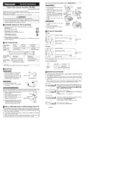
SOLDERING (Connector type only)
4
1.5mm
Soldering position
0V OUT +V
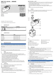
●
When xing the sensor with screws, use M3 screws and
the tightening torque should be 0.49N m or less. Fur-・
thermore, use small, round type plain washers ( 6mm).φ
MOUNTING5
PM2 Series
Photoelectric Sensor
Micro-photosensor
This bag is a product made from polyethylene. Even if it burns, harmful gas is not generated.
●
●
Never use this product as a sensing device for personnel protection.
In case of using sensing devices for personnel protection, use products which meet
standards, such as OSHA, ANSI or IEC etc., for personnel protection applicable in each
region or country.
WARNING
I/O CIRCUIT DIAGRAMS3
100mA max.
Color code of cable type
and mainting cable
(B
lack ) Output
(Blue
) 0V
(Brown) + V
Internal circuit
Users' circuit
Sensor circuit
Load
+
-
5 to 24V DC
±10%
INTENDED PRODUCTS FOR CE MARKING
6
●The models listed under ' SPECIFICA-
TIONS' come with CE Marking. As for all
other models, please contact our oce.
1
PRINTED IN JAPAN © Panasonic Electric Works SUNX Co., Ltd. 2011
Overseas Sales Division (Head Office)
2431-1 Ushiyama-cho, Kasugai-shi, Aichi, 486-0901, Japan Phone: +81-568-33-7861 FAX: +81-568-33-8591
Europe Headquarter: Panasonic Electric Works Europe AG
Rudolf-Diesel-Ring 2, D-83607 Holzkirchen, Germany Phone: +49-8024-648-0
US Headquarter: Panasonic Electric Works Corporation of America
629 Central Avenue New Providence, New Jersey 07974 USA Phone: +1-908-464-3550
http://panasonic-electric-works.net/sunx
Product specificaties
| Merk: | Panasonic |
| Categorie: | Niet gecategoriseerd |
| Model: | PM2LF10 |
Heb je hulp nodig?
Als je hulp nodig hebt met Panasonic PM2LF10 stel dan hieronder een vraag en andere gebruikers zullen je antwoorden
Handleiding Niet gecategoriseerd Panasonic

29 Juli 2025

5 Juli 2025

23 Mei 2025
16 Mei 2025

2 Mei 2025
28 April 2025
17 April 2025

17 April 2025

17 April 2025
16 April 2025
Handleiding Niet gecategoriseerd
- Olympia
- Storm
- Taga Harmony
- Master Lock
- Act
- Schuberth
- Zennio
- Monacor
- Koenic
- Pinolino
- Autotek
- Wahoo
- KKT Kolbe
- Britax-Romer
- UNYKAch
Nieuwste handleidingen voor Niet gecategoriseerd

1 Augustus 2025

1 Augustus 2025
1 Augustus 2025

1 Augustus 2025
1 Augustus 2025
1 Augustus 2025
1 Augustus 2025

1 Augustus 2025
1 Augustus 2025

1 Augustus 2025