Panasonic NA1PK3PN Handleiding
Panasonic
Niet gecategoriseerd
NA1PK3PN
Bekijk gratis de handleiding van Panasonic NA1PK3PN (2 pagina’s), behorend tot de categorie Niet gecategoriseerd. Deze gids werd als nuttig beoordeeld door 11 mensen en kreeg gemiddeld 4.5 sterren uit 6 reviews. Heb je een vraag over Panasonic NA1PK3PN of wil je andere gebruikers van dit product iets vragen? Stel een vraag
Pagina 1/2
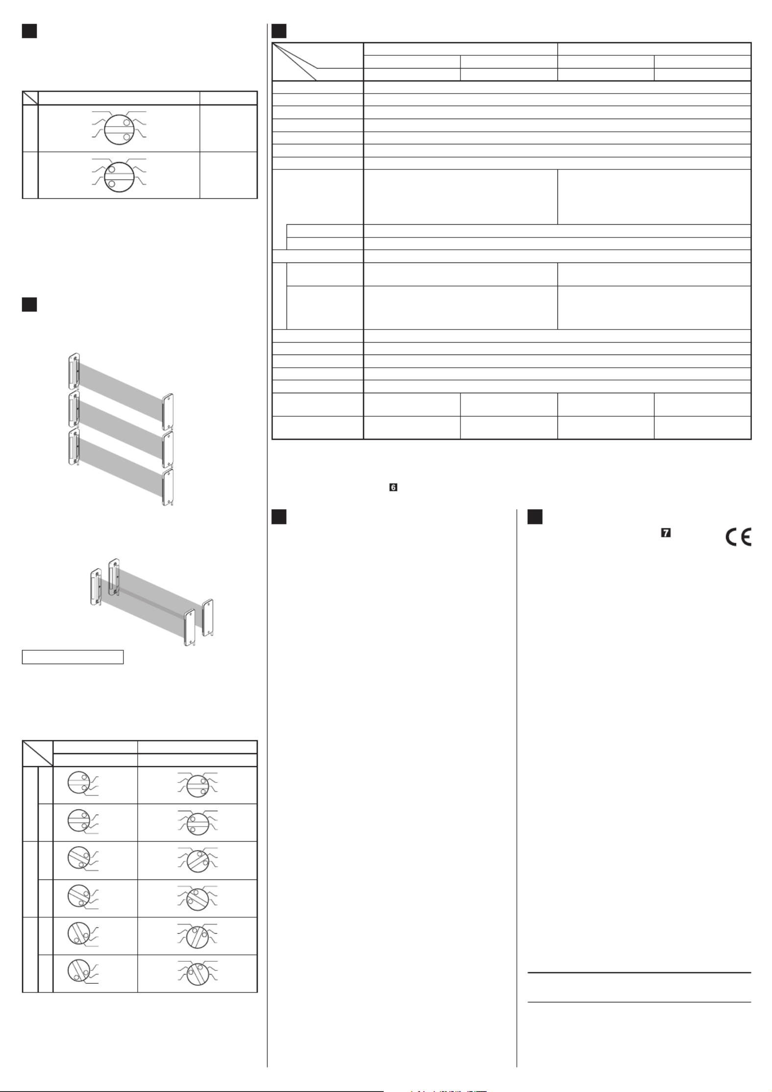
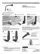
<PNP output type>
Internal circuit Users' circuit
Color code /
Connector pin No. of the pigtailed type
(Brown / 1) +V
(Note 2)
(Blue / 3) 0V
(Black / 4) Output (Note 1)
100mA max.
1
Job indicator
lighting circuit
Load
+
-
12 to 24V DC
±10%
(Pink / 2) Job
indicator input
Main circuit
3
0V
2
Job indicator input
1
+V
4
Output (Note)
Connector-pin position (Pigtailed type)Ɣ
Notes: 1) The output is not incorporated in the emitter.
2) When the job indicator is used as a large size op-
eration indicator, connect the job indicator input wire
(pink) of the emitter and receiver to the output wire
(black) of the receiver.
*1
or
Non-voltage contact or PNP open-collector transistor
High (4 to 30V DC): Lights up
Low (0 to 0.6V DC or Open): Lights off
Note: No connection is required for the emitter.
BEAM ALIGNMENT
4
1. Place the emitter and the receiver face to face
along a straight line.
2. After the cables have been correctly connected,
switch the power ON.
3. Move the emitter in the up, down, left and right
directions, in order to determine the range of
the beam received condition with the help of the
operation indicator (red) on the receiver. Then,
set the emitter at the center of this range.
4. Similarly, adjust for up, down, left and right an-
gular movement of the emitter.
5. Further, perform the angular adjustment for the
receiver also.
6. Check that the stable incident beam indicator
(green) lights up.
7. Interrupt each beam channel with the actual
VHQVLQJREMHFWDQGFRQ¿UPWKDWWKHVHQVRURS-
erates correctly.
Note: The stable incident beam indicator (green) lights up
when all the three beams are stably received by the
receiver.
Emitter
Receiver
Stable incident beam
indicator (Green)
Operation indicator
(Red)
INSTRUCTION MANUAL
NA1-PK3 Series
Thank you very much for using SUNX products.
Please read this Instruction Manual carefully and
thoroughly for the correct and optimum use of
this product. Kindly keep this manual in a conve-
nient place for quick reference.
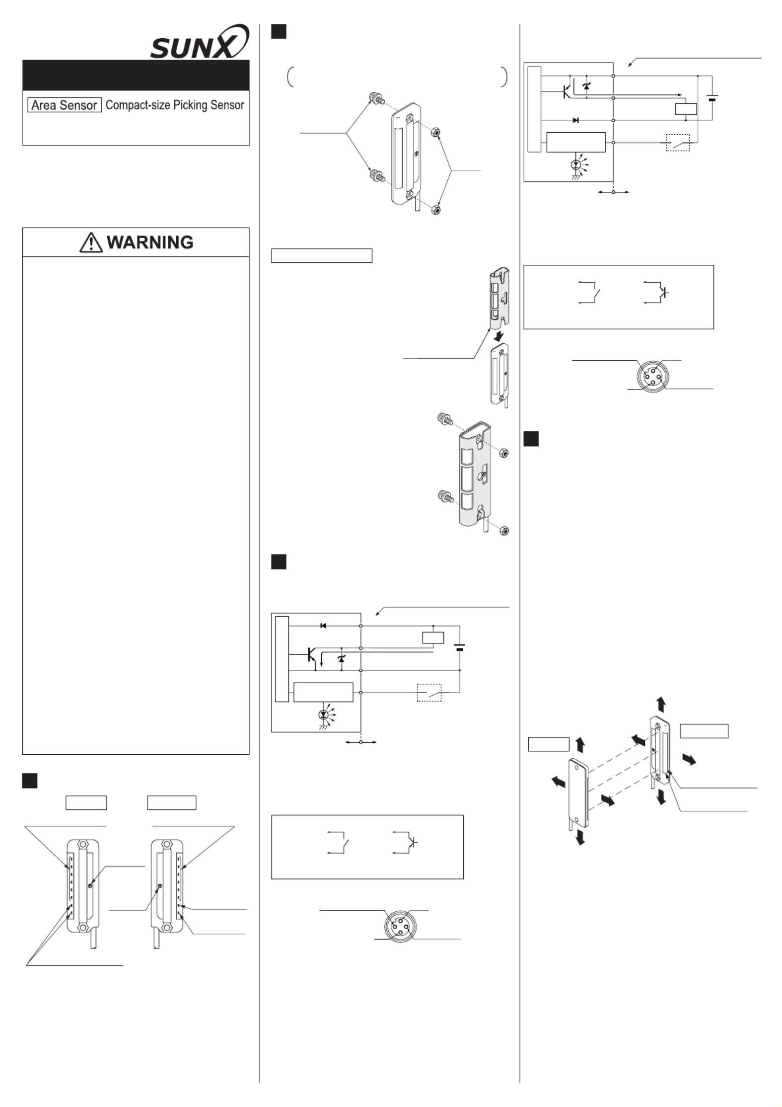
PART DESCRIPTION
1
Job indicators (Orange)
Emitter Receiver
Job indicators (Orange)
Power indicator (Green)
Frequency
selection
switch
Operation /
frequency
selection
switch
Stable incident
beam indicator
(Green)
Operation
indicator (Red)
If this product is used as a sensing de-
vice for personnel protection, serious
body injury or death could result.
Never use this product as a sensing device
with any press machine, shearing machine,
roll grinding machine, forming machine, vul-
canizer, or robot etc. for protection of a hand
or a part of the body.
This product does not include a self-check-
ing circuit for safety functions necessary
to allow its use as a safety device. Thus, a
system failure or malfunction can result in
either an energized or a de-energized output
condition.
When this product is used as a sensing
device in the following applications and if a
problem relating to “law” or “product liability”
occurs, SUNX shall not be liable for the fail-
ure and for the damage or less.
1) Use of this product installed to a machin-
ery or a device as a sensing device to
detect a hand or a part of the operator’s
body entering a dangerous area and stop
the machinery or the device.
2) Installation of this product to a protection
device for preventing to enter a dangerous
area and use of this as a sensing device
which detects a hand or a part of the op-
erator’s body and open / close the door or
window.
3) Use of this product as a sensing device for
personnel protection (including interlock).
For sensing devices to be used as safety
devices for press machines or for person-
nel protection, use products which meet
standards, such as OSHA, ANSI or IEC etc.,
for personnel protection applicable in each
region or country.
In case of using as a safety device for press
machine, use a product approved by the
Ministry of Health, Labor and Welfare in Ja-
pan.
Ɣ
Ɣ
Ɣ
Ɣ
Ɣ
Ɣ
Job indicator
lighting circuit
Internal circuit Users' circuit
(Brown / 1) +V
(Blue / 3) 0V
(Note 2)
100mA max.
1
Load +
-
12 to 24V DC
±10%
Color code /
Connector pin No. of the pigtailed type
(Pink / 2) Job
indicator input
(Black / 4) Output
(Note 1)
Main circuit
<NPN output type>
I/O CIRCUIT DIAGRAMS
3
3
0V
2
Job indicator input
1
+V
4
Output (Note)
Connector-pin position (Pigtailed type)Ɣ
*1
or
Non-voltage contact or NPN open-collector transistor
Low (0 to 2V DC): Lights up
High (5 to 30V DC or Open): Lights off
Note: No connection is required for the emitter.
Notes: 1) The output is not incorporated in the emitter.
2) When the job indicator is used as a large size op-
eration indicator, connect the job indicator input wire
(pink) of the emitter and receiver to the output wire
(black) of the receiver.
MOUNTING
2
M4 screws
with washers
M4 nuts
The sensor protection bracket (MS-NA3-3) (op-
tional) is also available.
Ɣ
Sensor protection
bracket ( )MS-NA3-3
(Optional)
Mounting method
1.
Insert the sensor protec-
tion bracket (MS-NA3-3)
from upwards of the sen-
sor body, and match the
position of the mounting
holes of the sensor body
and the sensor protec-
tion bracket (MS-NA3-3).
2.
M o u n t w i t h t h e M 4
screws with washers and
the M4 nuts enclosed
with the sensor protec-
tion bracket ( ).MS-NA3-3
The tightening torque
should be 0.5N·m or
less.
Use M4 screws with washers and M4 nuts. The
tightening torque should be 0.5N·m or less.
Please arrange the screws and the nuts
separately.
Ɣ
SELECTION OF OUTPUT OPERATION
5
The output operation can be selected by the
operation / frequency selection switch on the
receiver. (Make sure to set the switch in the
power supply off condition.)
Ɣ
State of operation / frequency selection switch
Output operation
L-ON
L - O N
FREQ.
D - O N
FREQ.
3
2
1
3
2
1
OFF whe n
one or more
bea ms are
interrupted.
D-ON
O N w h e n
one or more
bea ms are
interrupted.
L - O N
FREQ.
D - O N
FREQ.
3
2
1
3
2
1
Notes: 1) Selection of the output operation and the frequency
for the receiver is carried out with the same switch.
When the output operation is set, be sure to select
the same frequency No. of the emitter and the re-
ceiver.
2) In case the operation / frequency selection switch is
set to the position other than 1, 2 or 3, the state of
the receiver is in D-ON / frequency 1.
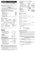
INTERFERENCE PREVENTION FUNCTION
6
By setting different emission frequencies, three
sets of the sensors can be mounted closely as
VKRZQLQWKH¿JXUHEHORZ
Ɣ
Sensor 1
Sensor 2
Sensor 3
However, if the sensors are mounted closely as
VKRZQLQWKH¿JXUHEHORZXSWR VHWVRIVHQ-
sors are possible.
Ɣ
Sensor 1
Sensor 2
Set the both emitting and receiving frequency
of Sensor 1 to FREQ. 1, the both emitting and
receiving frequency of Sensor 2 to FREQ. 2
and the both emitting and receiving frequency
of Sensor 3 to FREQ. 3. (Make sure to set the
switch in the power supply off condition.)
Ɣ
Frequency setting
Emitter Receiver
Frequency selection switch Operation / Frequency selection switch
Sensor 1
L-ON
FREQ.
3
2
13
2
1
3
2
1
L - O N
FREQ.
D - O N
FREQ.
D-ON
FREQ.
3
2
13
2
1
3
2
1
L- ON
FREQ.
D - ON
FREQ.
Sensor 2
L-ON
FREQ.
3
2
13
2
1
3
2
1
L - O N
FREQ.
D - O N
FREQ.
D-ON
FREQ.
3
2
13
2
1
3
2
1
L - O N
FREQ.
D - O N
FREQ.
Sensor 3
L-ON
FREQ.
3
2
13
2
1
3
2
1
L- ON
FREQ.
D - ON
FREQ.
D-ON
FREQ.
3
2
13
2
1
3
2
1
L - O N
FREQ.
D - O N
FREQ.
Notes: 1) Take care that selection of the output operation and
the frequency for the receiver is carried out with the
same switch.
2) In case the frequency switch and the operation / fre-
quency selection switch is set to the position other
than 1, 2 or 3, the state of the emitter is in frequency
1 and that of the receiver is in D-ON / frequency 1.
7SPECIFICATIONS
Type NPN output PNP output
2m cable length type 5m cable length type 2m cable length type 5m cable length type
Item
Model No. (Note 1)
NA1-PK3
NA1-PK3-C5 NA1-PK3-PN NA1-PK3-PN-C5
Sensing height 49.2mm
Sensing range 30 to 300mm
Beam pitch 24.6mm
Number of beam channels
3 beam channels
Sensing object ø29mm or more opaque object
Supply voltage 12 to 24V DC±10% Ripple P-P10% or less
Current consumption Emitter: 30mA or less, Receiver: 50mA or less
Output
NPN open-collector transistor
Maximum sink current: 100mA
Applied voltage: 30V DC or less (between output and 0V)
Residual voltage: 1V or less (at 100mA sink current)
0.4V or less (at 16mA sink current)
•
•
•
PNP open-collector transistor
Maximum source current: 100mA
Applied voltage: 30V DC or less (between output and +V)
Residual voltage: 1V or less (at 100mA source current)
0.4V or less (at 16mA source current)
•
•
•
Output operation ON or OFF when one or more beam channels are interrupted, selectable by a switch
Short-circuit protection
Incorporated
Response time 10ms or less (when interference prevention is used: 30ms or less)
Indicators
Emitter
Power indicator: Green LED (lights up when the power is ON)
Job indicator: Orange LED (lights up when the job indicator input is Low)
Power indicator: Green LED (lights up when the power is ON)
Job indicator: Orange LED (lights up when the job indicator input is High)
Receiver
Operation indicator: Red LED (lights up when the output is ON)
Stable incident beam indicator: Green LED
(lights up when the all beams are stably received)
Job indicator: Orange LED (lights up when the job indicator input is Low)
Operation indicator: Red LED (lights up when the output is ON)
Stable incident beam indicator: Green LED
(lights up when the all beams are stably received)
Job indicator: Orange LED (lights up when the job indicator input is High)
Interference prevention function
Incorporated (Up to 3 units can be closely mounted) (Note 2)
Ambient temperature –10 to +55°C (No dew condensation or icing allowed), Storage: –20 to +70°C
Ambient humidity 35 to 85% RH, Storage: 35 to 85% RH
Emitting element Infrared LED (synchronized scanning system)
Material Enclosure: Heat-resistant ABS, Lens cover: Acrylic, Display cover: Acrylic
Cable
0.2mm24-core (emitter: 3-core)
oil resistant cabtyre cable, 2m long
0.2mm
24-core (emitter: 3-core)
oil resistant cabtyre cable, 5m long
0.2mm24-core (emitter: 3-core)
oil resistant cabtyre cable, 2m long
0.2mm24-core (emitter: 3-core)
oil resistant cabtyre cable, 5m long
Weight Emitter: Approx. 50g
Receiver: Approx. 50g
Emitter: Approx. 105g
Receiver: 110g
Emitter: Approx. 50g
Receiver: Approx. 50g
Emitter: Approx. 105g
Receiver: 110g
1RWHV 7KHPRGHO1RZLWKVXI¿[³-J” is pigtailed type. (cable length: 0.3m)
Model No.: NA1-PK3(-PN)-J
For the cable connected with the pigtailed type, use the connection cable CN-24-C2 (cable length: 2m) (optional) or
CN-24-C5 (cable length: 5m) (optional).
2) For details, refer to “ INTERFERENCE PREVENTION FUNCTION.”
PRINTED IN JAPAN
Overseas Sales Dept. (Head Office)
2431-1 Ushiyama-cho, Kasugai-shi, Aichi, 486-0901, Japan
Phone: +81-(0)568-33-7861 FAX: +81-(0)568-33-8591
Europe Headquarter: Panasonic Electric Works Europe AG
Rudolf-Diesel-Ring 2, D-83607 Holzkirchen, Germany
Phone: +49-8024-648-0
US Headquarter: Panasonic Electric Works Corporation of America
629 Central Avenue New Providence, New Jersey 07974 USA
Phone: +1-908-464-3550
URL : sunx.jp
SUNX Limited
This product has been developed / produced for
industrial use only.
Make sure that the power supply is off while wir-
ing and operation of the selection switch.
Take care that wrong wiring may damage the sensor.
Verify that the supply voltage variation is within
the rating.
If power is supplied from a commercial switch-
ing regulator, ensure that the frame ground
(F.G.) terminal of the power supply is connected
to an actual ground.
Do not use during the initial transient time (0.5
sec.) after the power supply is switched on.
In case noise generating equipment (switching
regulator, inverter motor, etc.) is used in the vicin-
ity of the sensor, connect the frame ground (F.G.)
terminal of the equipment to an actual ground.
Extension up to total 100m is possible with
0.3mm2, or more, cable for both emitter and re-
ceiver. However, in order to reduce noise, make
the wiring as short as possible.
Do not run the wires together with high-voltage lines
or power lines or put them in the same raceway.
This can cause malfunction due to induction.
Take care that the sensor is not directly exposed
WRÀXRUHVFHQWODPSIURPDUDSLGVWDUWHUODPSD
high frequency lighting device or sunlight etc.,
as it may affect the sensing performance.
Avoid dust, dirt, and steam.
Take care that the product does not come in
contact with water, oil, grease, organic solvents,
such as thinner, etc., strong acid or alkaline.
Make sure to use an isolation transformer for
the DC power supply. If an auto-transformer
(single winding transformer) is used, this prod-
uct or the power supply may get damaged.
In case a surge is generated in the used power
supply, connect a surge absorber to the supply
and absorb the surge.
The emitter and the receiver must face each
other correctly. If they are set upside down, the
sensor does not work.
,QRUGHU WRWXUQWKHVZLWFKHVDÀDWKHDGVFUHZ-
driver is required. (The blade should be 2.5 ×
0.6mm or less)
This sensor is suitable for indoor use only.
Ɣ
Ɣ
Ɣ
Ɣ
Ɣ
Ɣ
Ɣ
Ɣ
Ɣ
Ɣ
Ɣ
Ɣ
Ɣ
Ɣ
Ɣ
Ɣ
Ɣ
CAUTIONS
8
INTENDED PRODUCTS FOR CE MARKING
9
The models listed under “ SPEC-
IFICATIONS” come with CE Mark-
ing.
As for all other models, please con-
WDFWRXURI¿FH
Ɣ
Product specificaties
| Merk: | Panasonic |
| Categorie: | Niet gecategoriseerd |
| Model: | NA1PK3PN |
Heb je hulp nodig?
Als je hulp nodig hebt met Panasonic NA1PK3PN stel dan hieronder een vraag en andere gebruikers zullen je antwoorden
Handleiding Niet gecategoriseerd Panasonic

29 Juli 2025

5 Juli 2025

23 Mei 2025

16 Mei 2025

2 Mei 2025
28 April 2025

17 April 2025

17 April 2025

17 April 2025

16 April 2025
Handleiding Niet gecategoriseerd
- Aqua Marina
- EBERLE
- Paingone
- Tributaries
- Monogram
- Nutrichef
- Tristar
- HTW
- Riello
- HomePilot
- Salus
- Jan Nowak
- Brigmton
- 2N Telecommunications
- Terraillon
Nieuwste handleidingen voor Niet gecategoriseerd

31 Juli 2025

31 Juli 2025

31 Juli 2025

31 Juli 2025
31 Juli 2025

31 Juli 2025

31 Juli 2025

31 Juli 2025
31 Juli 2025

31 Juli 2025