Panasonic LC4H Handleiding
Bekijk gratis de handleiding van Panasonic LC4H (9 pagina’s), behorend tot de categorie Niet gecategoriseerd. Deze gids werd als nuttig beoordeeld door 18 mensen en kreeg gemiddeld 4.4 sterren uit 9.5 reviews. Heb je een vraag over Panasonic LC4H of wil je andere gebruikers van dit product iets vragen? Stel een vraag
Pagina 1/9

76
DIN 48 SIZE
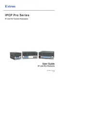
LCD ELECTRONIC COUNTER LC4H
FEATURES
1. Bright and Easy-to-Read Display
A brand new bright 2-color backlight LCD
display. The easy-to-read screen in any
location makes checking and setting pro-
cedures a cinch.
2. Simple Operation
Seesaw buttons make operating the unit
even easier than before.
3. Short Body of only 64.5 mm 2.539
inch (screw type) or 70.1 mm 2.760
inch (pin type)
With a short body, it easily installs in
even narrow control panels.
4. Conforms to IP66’s Weather
Resistant Standards
The water-proof panel keeps out water
and dirt for reliable operation even in
poor environments.
5. Screw terminal and Pin Type are
Both Standard Options
The two terminal types are standard
options to support either front panel
installation or embedded installation.
6. Changeable Panel Cover
Also offers a black panel cover to meet
your design considerations.
7. 4-digit or 6-digit display
Two sizes of displays are offered for you
to choose the one that suits your needs.
8. Conforms With EMC and Low
Voltage Directives
Conforms with EMC directives
(EN50081-2/EN50082-2) and low-volt-
age directives (VDE0435/Part 2021) for
CE certification vital for use in Europe.
48
1.890
48
1.890
64.5
2.539
R4/T4 systems (4-digit display)
R6/T6 systems (6-digit display)
Pin type Screw terminal type
Digit Count speed Operation voltage Power down insurance Part No.Output mode Output Terminal
4
6
30 Hz (cps)/
5 KHz (Kcps)
switchable
• Maintain
output/hold count
• Maintain
output/over count I
• Maintain
output/over count II
• One shot/over
count
• One shot/recount I
• One shot/recount II
• One shot/hold
count
(7 modes)
Relay
(1c)
Transistor
(1a)
Relay
(1c)
Transistor
(1a)
100-240 V AC
12-24 V DC
100-240 V AC
12-24 V DC
100-240 V AC
12-24 V DC
100-240 V AC
12-24 V DC
24 V AC / 24 V DC
24 V AC / 24 V DC
24 V AC / 24 V DC
24 V AC / 24 V DC
Available
11 pin
Screw
11 pin
Screw
11 pin
Screw
11 pin
Screw
11 pin
Screw
11 pin
Screw
11 pin
Screw
11 pin
Screw
LC4H-R4-AC240V
LC4H-R4-AC240VS
LC4H-R4-DC24V
LC4H-R4-DC24VS
LC4H-T4-AC240V
LC4H-T4-AC240VS
LC4H-T4-DC24V
LC4H-T4-DC24VS
LC4H-R6-AC240V
LC4H-R6-AC240VS
LC4H-R6-DC24V
LC4H-R6-DC24VS
LC4H-T6-AC240V
LC4H-T6-AC240VS
LC4H-T6-DC24V
8 pin
8 pin
8 pin
8 pin
8 pin
8 pin
8 pin
8 pin
LC4H8-R4-AC240V
LC4H8-R4-DC24V
LC4H8-T4-AC240V
LC4H8-T4-DC24V
LC4H8-R6-AC240V
LC4H8-R6-DC24V
LC4H8-T6-AC240V
LC4H8-T6-DC24V
LC4H-T6-DC24VS
11 pin
Screw
11 pin
Screw
11 pin
Screw
11 pin
Screw
LC4H-R4-AC24V
LC4H-R4-AC24VS
LC4H-T4-AC24V
LC4H-T4-AC24VS
LC4H-R6-AC24V
LC4H-R6-AC24VS
LC4H-T6-AC24V
8 pin
8 pin
8 pin
8 pin
LC4H8-R4-AC24V
LC4H8-T4-AC24V
LC4H8-R6-AC24V
LC4H8-T6-AC24V
LC4H-T6-AC24VS
PRODUCT TYPES
LC4H
* A rubber gasket (ATC18002) and a mounting frame (AT8-DA4) are included.
mm inch
02/2003

77
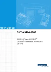
PART NAMES
UP
DOWN
RESET
LOCK
C O U N T E R L C 4 H
OP.
RS T
LOCK
Controlled output indicator
Reset indicator
Lock indicator
Reset switch
Lock switch
Counter display
Set value display
Up keys
Down keys
O N
1234567 8
DIP switches
(Same for screw-down terminal type)
RESET
LOCK
C O U N T E R L C 4 H
OP.
RS T
LOCK
Controlled output indicator
Reset indicator
Lock indicator
Reset switch
Lock switch
Counter display
Set value display
Up keys
O N
1234567 8
DIP switches
(Same for screw-down terminal type)
SPECIFICATIONS
Item Ralay output type
AC type
100 to 240 V AC, 24 V AC1)
50/60 Hz common
Max. 10 V A
1 Form C: 5 A, 250 V AC (resistive)
Addition (UP)/Subtraction (DOWN)/Direction (DIR)/Individuality (IND)/Phase (PHASE)
5 modes selectable by DIP switch
30 Hz/5 kHz (selectable by DIP switch)
16.7 ms at 30 Hz/0.1 ms at 5 kHz ON time: OFF time = 1:1
Signal reset/Push-key switch, Min. input time 1 ms, 20 ms (selected by DIP switch)
Min. input signal width: 20 ms
Contact or Open collector input/Input impedance: 1 k or less, Input residual voltage: 2 V or less,Ω
Open impedance: 100 k or more, Max. energized voltage: 40 V DCΩ
HOLD-A/HOLD-B/HOLD-C/SHOT-A/SHOT-B/SHOT-C/SHOT-D, 7 modes selectable by DIP switch
Approx. 1 s
7-segment LCD, Counter value (backlight red LED), Setting value (backlight yellow LED)
4-digit display type –999 to 9999 (–3 digits to +4 digits) (0 to 9999 for setting)
6-digit display type –99999 to 999999 (–5 digits to 6 digits) (0 to 999999 for setting)
EEP-ROM (Overwriting times: 105ope. or more)
1 Form C
100 mΩ(at 1 A 6 V DC)
Ag alloy/Au flush
2.0 10×7ope. (Except for switch operation parts)
1.0 10×5ope. (At rated control voltage)
85 to 110 % of rated operating voltage
Between live and dead metal parts: 2,000 Vrms for 1 min (11-pin type)
Between input and output: 2,000 V AC for 1 min
Between live and dead metal parts: 2,000 Vrms for 1 min (11-pin type)
Between input and output: 2,000 Vrms for 1 min
Between open contacts: 1,000 Vrms for 1 min
Between live and dead metal parts: Min. 100 M (11-pin type)Ω
Between input and output: Min. 100 MΩ
Between open contact: Min. 100 MΩ
Between live and dead metal parts: Min. 100 M (11-pin type)Ω
Between input and output: Min. 100 MΩ
Max. 65° C (under the flow of nominal operating current at nominal voltage)
10 to 55 Hz (1 cycle/min), single amplitude: 0.35 mm (10 min on 3 axes).014 inch
10 to 55 Hz (1 cycle/min), single amplitude: 0.75 mm (1 h on 3 axes).030 inch
1 Form A (Open collector)
—
—
—
1.0 10×7ope. (At rated control voltage)
12 to 24 V DC
—
Max. 3 W
100 to 240 V AC, 24 V AC1)
50/60 Hz common
Max. 10 V A
1 Form A: 100 mA, 30 V DC Open collector output (Max.)
12 to 24 V DC
—
Max. 3 W
DC type
Transistor output type
AC type DC type
Rating
Contact
Life
Electrical
Mechanical
Operating
conditions
Rated operating voltage
Rated frequency
Power consumption
Control output
Input mode
Counting speed
Min. counting input time
Reset input method
Lock input
Input signal
Output mode
One shot output time
Indication
Digit
Memory
Contact arrangement
Initial contact resistance
Contact material
Mechanical
Electrical
Operating voltage range
Initial withstand voltage
Initial insulation resistance
(At 500 V DC)
Temperature rise
Functional
Destructive
Vibration
resistance
Min. 98 m /s321.522 ft. 2(4 times on 3 axes)
Min. 294 m /s964.567 ft. 2(5 times on 3 axes)
–10° C to 55° C +14° F to +131° F
Max. 85 % RH
860 to 1,060 h Pa
—
8-pin/11-pin/screw terminal
IP66 (front panel with a rubber gasket)
20 % or less — 20 % or less
Functional
Destructive
Ambient temperature
Ambient humidity
Air pressure
Ripple rate
Connection
Protective construction
Shock
resistance
LC4H
Note: 1) the 24 V AC type can be operated also with 24 V DC.
02/2003

78
DIMENSIONS (units: mm inch)
• LC4H electrical counter
TERMINAL LAYOUT AND WIRING
• 8 pin type
Relay output type Transistor output type
• Screw-down terminal type
Relay output type Transistor output typeRelay output type Transistor output type
• 11 pin type
• Dimensions for embedded installation (with adapter installed)
•
Dimensions for front panel installations
•
Installation panel cut-out dimensions
The standard panel cut-out dimensions are shown
below. Use the installation frame (AT8-DA4) and
rubber gasket (ATC18002).
• For connected installations
Note 1: The installation panel thickness should be between 1
and 5 mm .039 and .197 inch.
Note 2: For connected installations, the waterproofing ability
between the unit and installation panel is lost.
Screw-down terminal type
(embedded installation)
Screw-down terminal type Pin type
Pin type (embedded installation/
front panel installation)
Screw-down terminal type
(embedded installation)
Pin type (embedded installation/
front panel installation)
UP
DOWN
RESET
LOCK
COUN TER LC 4H
OP.
R S T
LO CK
48
1.890
48
1.890
48
1.890
48
1.890
50
1.969
RESET
LOCK
COUN T ER LC4H
OP.
R S T
LO CK
66
2.598
63.5
2.500
1
.039
Installation frame for
embedded installations
AT8-DA4 (supplied)
Installation frame
for embedded
installations
ATA4811 (supplied)
Installation panel
Rubber gasket
ATC18002 (supplied)
66
2.598
Installation panel
Rubber gasket
ATC18002 (supplied)
50
1.969
1
.039
(44.5
(1.752
90
3.543
(11p cap AT8-DP11
sold separately)
(8p cap AD8-RC
sold separately)
11-pin type
8-pin type
DIN rail terminal block
ATC18004 or ATC18003
(sold separately)
Device installation rail
AT8-DLA1
(sold separately)
( ) Dimensions for 8-pin type.
95.5
(90.0)
3.760
(3.543)
80 min.
3.150
80 min.
3.150
45-0.6
0
45-0.6
0
1.772-.024
0
1.772-.024
0
A
A = (48 n – 2.5) ×–0.6
0
45-0.6
0
1.772-.024
0
1
2
3
4
567
8
9
1 0
1 1
Reset
Input 1
Input 2
Lock
COM
NC
NO
Operation voltage (+)( )–
1
2
3
4
567
8
9
1 0
1 1
Reset
Input 1
Input 2
Lock
Operation voltage (+)( )–
8
5
1
7
6
2
3
4
COM
NO
Operation voltage (+)( )–
Reset
Input 1
Input 2
8
5
1
7
6
2
3
4
Operation voltage (+)( )–
Reset
Input 1
Input 2
1 2 3 4 5
6 7 8 9 1 0
NO NC
COM
Reset
Input 1
Input 2
Lock
Operation voltage
( )(+) –
1 2 3 4 5
6 7 8 9 1 0
Reset
Input 1
Input 2
Lock
Operation voltage
( )(+) –
LC4H
Note: For connecting the output leads of the transistor output type, refer to 6) Transistor output on page 99.
UP
DOWN
RESET
LOCK
COUN T ER LC 4 H
48
1.890
48
1.890
5.5
.217
70.1
2.760
55.6
2.189
7.5
.295
(44.5
(1.752
5.5
.217 64.5
2.539
7.5
.295
(44.5
(1.752
48
1.890
RESET
LOCK
C OU NT E R LC 4 H
48
1.890
70.1
2.760
55.6
2.189
5.5
.216 64.5
2.539
7.5
.295
5.5
.217
7.5
.295
(44.5
(1.752
(44.5
(1.752
02/2003
Product specificaties
| Merk: | Panasonic |
| Categorie: | Niet gecategoriseerd |
| Model: | LC4H |
Heb je hulp nodig?
Als je hulp nodig hebt met Panasonic LC4H stel dan hieronder een vraag en andere gebruikers zullen je antwoorden
Handleiding Niet gecategoriseerd Panasonic

29 Juli 2025

5 Juli 2025
23 Mei 2025
16 Mei 2025

2 Mei 2025
28 April 2025

17 April 2025

17 April 2025

17 April 2025
16 April 2025
Handleiding Niet gecategoriseerd
- Littelfuse
- Novy
- EPEVER
- Tru Components
- Irritrol
- SetonixSynth
- Gerber
- AMS Office
- Greenworks
- Brandson
- EmberGlo
- TCW Technologies
- GR Bass
- LawnMaster
- Tower
Nieuwste handleidingen voor Niet gecategoriseerd
31 Juli 2025
31 Juli 2025

31 Juli 2025

31 Juli 2025
31 Juli 2025
31 Juli 2025

31 Juli 2025
31 Juli 2025
31 Juli 2025
31 Juli 2025