Panasonic EX14BPN Handleiding
Panasonic
Niet gecategoriseerd
EX14BPN
Bekijk gratis de handleiding van Panasonic EX14BPN (1 pagina’s), behorend tot de categorie Niet gecategoriseerd. Deze gids werd als nuttig beoordeeld door 80 mensen en kreeg gemiddeld 4.7 sterren uit 40.5 reviews. Heb je een vraag over Panasonic EX14BPN of wil je andere gebruikers van dit product iets vragen? Stel een vraag
Pagina 1/1

Note: Excluding EX-19.
"2mm opaque object
Setting distance between
emitter and receiver: 1m
"2mm opaque object
(Setting distance between emitter and receiver: 500mm)
"1mm opaque object
(Setting distance between emitter and receiver: 150mm)
Model No.
MS-EX10-1
MS-EX10-2
MS-EX10-3
MS-EX10-11
MS-EX10-12
MS-EX10-13
Description
Mounting bracket for front sensing type only
Two M2 (length 4mm) pan head screws are
attached.
Mounting bracket for side sensing type only
Two M2 (length 8mm) pan head screws are
attached.
L-shaped mounting bracket
Two M2 (length 4mm) pan head screws, and two
M2 (length 8mm) pan head screws are attached.
Mounting bracket for front sensing type only
Two M2 (l en gt h 4mm) pan hea d screws
(stainless steel) are attached.
Mounting bracket for side sensing type only
Two M2 (l en gt h 8mm) pan hea d screws
(stainless steel) are attached.
L-shaped mounting bracket
Two M2 (l en gt h 4mm) pan hea d screws
(stainless steel), and two M2 (length 8mm) pan
head screws (stainless steel) are attached.
Material
Stainless
steel
(SUS304)
Cold
rolled
carbon
steel
(SPCC)
Apply a slit mask when detecting small objects or for
increasing the accuracy of sensing position. However,
the sensing range is reduced when the slit mask is
mounted.
The slit mask should be mounted on the sensor before
mounting the sensor.
If the front sensing type sensor is used along with the
slit mask and the optional sensor mounting bracket for
the front sensing type, MS-EX10-1 MS-EX10-11or , as
shown in the figure below, a 0.2mm, or more, thick
spacer is separately required.
M3 screws
0.2mm, or more, thick spacer
is separately required.
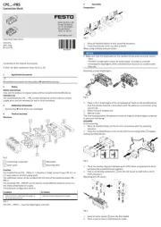
When mounting the sensor with the optional sensor
mounting bracket, use the attached M2 screws and the
tightening torque should be 0.2N m or less.
Six types of optional sensor mounting brackets are
available.
Material
This product is not a safety sensor. Its use is
not intended or designed to protect life and
prevent body injury or property damage from
dangerous parts of machinery. It is a normal
object detection sensor.
PRINTED IN JAPAN
http://www.sunx.co.jp/
Head Oce
SUNX Limited
Phone: 81-(0)568-33-7861 FAX: 81-(0)568-33-8591
Overseas Sales Dept.
2431-1 Ushiyama-cho, Kasugai-shi, Aichi, 486-0901, Japan
Phone: 81-(0)568-33-7211 FAX: 81-(0)568-33-2631
٨EX- , EX-A(-R)B(-R) /NPN output type
3I/O CIRCUIT DIAGRAMS
٨
In case of mounting on tapped holes (Unit: mm)
Side sensing
4MOUNTING
Users’ circuitInternal circuit
D
Color code
50mA max.
ZD
Tr
Load
(Brown) V
(Black) Output (Note)
(Blue) 0V
12 to 24V DC
10%
Sensor circuit
Note: The emitter of the thru-beam type sensor does not
incorporate the output.
٨EX- A-PN, EX- B-PN /PNP output type
Users’ circuitInternal circuit
D
Color code
50mA max.
ZD
Tr
Load
(Brown) V
(Black) Output (Note)
(Blue) 0V
12 to 24V DC
10%
Sensor circuit
The tightening torque should be 0.2N
m or less.
M20.4 holes
tapped 6 deep
Attached
screw
ƆM2
Ტlength 10
ᲣƇų
11
Sensing
direction
Front sensing
Side sensing Front sensing
ų
Sensing
direction
M20.4 holes
tapped 7 deep
ƆM2
Ტlength 8ᲣƇų
Attached
screw
11
٨
In case of using attached screws and nuts (Unit: mm)
The tightening torque should be 0.2N
m or less.
Thickness of
mounting plate
2 or less
Attached
screw
ƆM2
Ტlength 10 ᲣƇ
Thickness of
mounting plate
2.5 or less
Spring
washers
Nuts
Flat washers
ƆM2
Ტlength 8ᲣƇų
Attached
screw
Sensing
direction
Sensing
direction
11
11 ų
Symbols . . . D : Reverse supply polarity protection diode
ZD: Surge absorption zener diode
Tr : NPN output transistor
Note: The emitter of the thru-beam type sensor does not
incorporate the output.
Symbols . . . D : Reverse supply polarity protection diode
ZD: Surge absorption zener diode
Tr : PNP output transistor
5
OPTIONAL SENSOR MOUNTING BRACKET
6OPTIONAL SLIT MASK
(EX-13 and EX-19 only)
1SPECIFICATIONS
2CAUTIONS
Thru-beam
Convergent reflective
Front sensing Side sensing Front sensing Side sensing Front sensing Front sensing
EX-11A(-PN -R) EX-11EA(-PN -R) EX-13A(-PN -R) EX-13EA(-PN -R) EX-19A(-PN -R) EX-14A(-PN/ / / / / /-R)
EX-11B(-PN -R) EX-11EB(-PN -R) EX-13B(-PN -R) EX-13EB(-PN -R) EX-19B(-PN -R) EX-14B(-PN/ / / / / /-R)
Type
Light-ON
Dark-ON
0.05mm or less 0.1mm or less
12 to 24V DCd10%Ripple P-P10%or less
Emitter 10mA or less, Receiver: : 15mA or less 20mA or less
źEX- EX-A -R( ) and B -R( )
Ż
NPN open-collector transistor
ȷMaximum sink current: 50mA
ȷ
Applied voltage: 30V DC or less (between output and 0V)
ȷResidual voltage: 1V or less (at 50mA sink current)
0.4V or less (at 16mA sink current)
Incorporated
0.5ms or less
Red LED (lights up when the output is ON), located on the receiver for the thru-beam type sensor
IP67 (IEC)
25 to 55C (Note 3) (No dew condensation or icing allowed), Storage: 30 to 70C
35 to 85% RH, Storage: 35 to 85% RH
Red LED (modulated)
Enclosure: Polyethylene terephthalate, Lens: Polyalylate
0.1mm23-core (thru-beam type emitter: 2-core) cabtyre cable, 2m long (Note 4)
Emitter, receiver: 20g approx. each 20g approx.
Mounting screws: 2 sets
Sensing range
Min. sensing object
Hysteresis
Repeatability
(Perpendicular to sensing axis)
Supply voltage
Current consumption
Output
Short-circuit protection
Response time
Operation indicator
Stability indicator
Protection
Ambient temperature
Ambient humidity
Emitting element
Material
Cable
Weight
Accessories
150mm 500mm 1m
2 to 25mm
ᲢNote 2Უ
ᲢConv. point: 10mmᲣ
15%or less of
operation distance
"0.1mm copper wire
(Setting distance: 10mm)
Item
źEX- A-PN EX- B-PNand Ż
PNP open-collector transistor
ȷMaximum source current: 50mA
ȷ
Applied voltage: 30V DC or less (between output and V)
ȷResidual voltage: 1V or less (at 50mA source current)
0.4V or less (at 16mA source current)
Green LED (lights up under stable light received condition or stable dark condition),
located on the receiver for the thru-beam type sensor
Mounting screws:
1 set
Model
No.
(Note 1)
INSTRUCTION MANUAL
Thank you very much for using SUNX sensors. Please
read this Instruction Manual carefully and thoroughly for
the correct and optimum use of this sensor. Kindly keep
this manual in a convenient place for quick reference.
Notes: 1)
Model Nos. having the suffix ‘ -PN ’ are PNP output type. Further, model Nos. having suffix ‘-R ’ are inflection resistant cable type. (NPN output type only)
Notes: 2) The sensing range of the convergent reflective type sensor is specified for white non-glossy paper (50 50mm) as the object.
Notes: 3) 10 to 55C for the inflection resistant cable type.
Notes: 4) The inflection resistant type has a 0.1mm
23-core (thru-beam type emmitter: 2-core) inflection resistant cabtyre cable, 2m long.
Ტ Უ
For the convergent reflective type EX-14, if there is a
reflective object (e.g., a conveyor, etc.) in the background
of the sensing object, since it may affect the sensing, use
by keeping enough distance from the reflective object.
Make sure to carry out wiring in the power supply off
condition.
Take care that wrong wiring will damage the sensor.
Verify that the supply voltage variation is within the rating.
If power is supplied from a commercial switching regulator,
ensure that the frame ground (F.G.) terminal of the power
supply is connected to an actual ground.
In case noise generating equipment (switching regulator,
inverter motor, etc.) is used in the vicinity of the product,
connect the frame ground (F.G.) terminal of the equipment
to an actual ground.
Do not use during the initial transient time (50ms) after the
power supply is switched on.
Extension up to total 50m is possible with a 0.3mm
2, or
more, cable for, both, emitter and receiver.
Do not run the wires together with high-voltage lines or
power lines or put them in the same raceway. This can
cause a malfunction due to induction.
Take care that the sensor is not directly exposed to
fluorescent light from a rapid-starter lamp or a high frequency
lighting device, as it may affect the sensing performance.
Avoid dust, dirt, and steam.
Take care that the sensor does not come in direct contact with
water, oil, grease or organic solvents, such as, thinner, etc.
This sensor is suitable for indoor use only.
Make sure that stress is not applied directly to the sensor
cable joint.
Stainless
steel
(SUS304)
Ultra-slim Type Photoelectric Sensor Amplifier Built-in
EX-10 Series
Model No.
OS-EX10-12
OS-EX10-15
OS-EX10E-12
(Note)
Description
Slit mask for front sensing type only
(hole diameter: "1.2mm)
Slit mask for front sensing type only
(hole diameter: "1.5mm)
Slit mask for side sensing type only
(hole diameter: "1.2mm)
Product specificaties
| Merk: | Panasonic |
| Categorie: | Niet gecategoriseerd |
| Model: | EX14BPN |
Heb je hulp nodig?
Als je hulp nodig hebt met Panasonic EX14BPN stel dan hieronder een vraag en andere gebruikers zullen je antwoorden
Handleiding Niet gecategoriseerd Panasonic

29 Juli 2025

5 Juli 2025

23 Mei 2025
16 Mei 2025

2 Mei 2025
28 April 2025

17 April 2025

17 April 2025

17 April 2025
16 April 2025
Handleiding Niet gecategoriseerd
- AENO
- Ariston Thermo
- InAlto
- Nuance
- Tilta
- MooreCo
- FireAngel
- Powerplus
- Wharfedale
- Exagerate
- OKAY
- Needit
- Ibm
- Velleman
- Koenic
Nieuwste handleidingen voor Niet gecategoriseerd

1 Augustus 2025

1 Augustus 2025
1 Augustus 2025

1 Augustus 2025
1 Augustus 2025
1 Augustus 2025
1 Augustus 2025

1 Augustus 2025
1 Augustus 2025

1 Augustus 2025