Panasonic EX-13SEB-PN Handleiding
Panasonic
Niet gecategoriseerd
EX-13SEB-PN
Bekijk gratis de handleiding van Panasonic EX-13SEB-PN (3 pagina’s), behorend tot de categorie Niet gecategoriseerd. Deze gids werd als nuttig beoordeeld door 67 mensen en kreeg gemiddeld 4.6 sterren uit 34 reviews. Heb je een vraag over Panasonic EX-13SEB-PN of wil je andere gebruikers van dit product iets vragen? Stel een vraag
Pagina 1/3

1
MEUEN-EX10 V2.0
Thank you for purchasing products from Panasonic Electric Works SUNX
Co., Ltd. Please read this Instruction Manual carefully and thoroughly for
the correct and optimum use of this product. Kindly keep this manual in a
convenient place for quick reference.
This product has been developed / produced for industrial use only.
For the convergent reective type EX-14, maintain adequate distance
from reective objects in the background, e.g. conveyors, since they may
adversely effect sensing.
A thin 0.1mm2 cable is used for this product. Do not use excessive force
when pulling on the cable: it may cause cable to break.
Make sure that the power supply is o while wiring.
Incorrect wiring will damage the sensor.
Verify that the supply voltage including the ripple is within the rating.
Verify that the supply voltage variation is within the rating.
If power is supplied from a commercial switching regulator, ensure that
the frame ground (F.G.) terminal of the power supply is connected to an
actual ground.
In case noise generating equipment (switching regulator, inverter motor,
etc.) is used in the vicinity of this product, connect the frame ground
(F.G.) terminal of the equipment to an actual ground.
Do not run the wires together with high-voltage lines or power lines or put
them in the same raceway. This can cause malfunction due to induction.
You can extend the cable up to 50m max. with 0.3mm
2 or more cable for
both emitter and receiver. However, in order to reduce noise, make the
wiring as short as possible.
Do not use during the initial transient time (0.5s) after the power supply is
switched on.
Ensure that the sensor is not directly exposed to the following light
sources as they may adversely eect sensing performance: uorescent
light from a rapid-starter lamp, a high frequency lighting device, sunlight
etc.
This sensor is suitable for indoor use only.
Avoid dust, dirt and steam. Do not use this sensor in places having
excessive vapor, dust, etc., or where it may come in direct contact with
corrosive gas.
Take care that the sensor does not come in contact with oil, grease,
organic solvents such as thinner, etc., strong acid, or alkalines.
Do not apply stress directly to the sensor cable joint by forcibly bending
or pulling.
Since the cable end is not waterproof, do not use the sensor in an
application where water could seep in from the cable end.
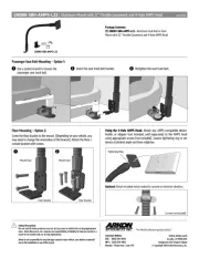
The tightening torque should be 0.2N·m or less.
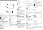
Mounting using tapped holes
Side sensing
Front sensing
When using the attached screws and nuts
Side sensing
Front sensing
INSTRUCTION MANUAL
Photoelectric Sensor Ultra-slim type
EX-10 Series
WARNING
• Never use this product as a sensing device for personnel protection.
• In case of using sensing devices for personnel protection, use
products which meet laws and standards, such as OSHA, ANSI or IEC
etc., for personnel protection applicable in each region or country.
1CAUTIONS
2MOUNTING
11mm
M2 x 0.4mm ø
10mm M2
6mm
Sensing direction
11mm
M2 x 0.4mm ø
7mm
8mm M2
Sensing direction
11mm
10mm M2
Thickness of mounting plate: 2mm or less
Flat washers
Spring washers
Sensing direction
11mm
8mm M2
Thickness of mounting plate: 2.5mm or less
Sensing direction
Flat washers
Spring washers

2
When mounting the sensor with the optional mounting bracket, use the
attached M2 screws. The tightening torque should be 0.2N·m or less.
Six types of optional sensor mounting brackets are available.
Optional slit masks help the sensor detect small objects. The accuracy of
the position being sensed is also increased. However, the sensing range is
reduced.
Attach the slit mask to the sensor before mounting the sensor.
If both the slit mask and the mounting bracket MS-EX10-1 or MS-EX10-11
are attached to the front sensing type sensor, use a spacer that is at least
0.2mm thick, as shown in the gure.
The following symbols are used in this section.
NPN output type
Only the thru-beam receiver incorporates the output.
PNP output type
Only the thru-beam receiver incorporates the output.
3MOUNTING BRACKETS
Model no. Description Material
MS-EX10-1 Mounting bracket for front sensing
type only.
Two 4mm M2 pan head screws
are attached.
MS-EX10-2 Mounting bracket for side sensing
type only.
Two 8mm M2 pan head screws
are attached.
Cold rolled car-
bon steel
(SPCC)
MS-EX10-3 L-shaped mounting bracket
Two 4mm and two 8mm M2 pan
head screws are attached.
MS-EX10-11 Mounting bracket for front sensing
type only.
Two 4mm M2 pan head screws
are attached.
MS-EX10-12 Mounting bracket for side sensing
type only.
Two 8mm M2 pan head screws
are attached.
Stainless steel
(SUS304)
MS-EX10-13 L-shaped mounting bracket
Two 4mm and two 8mm M2 pan
head screws are attached.
4SLIT MASKS
Model no. Description Material
OS-EX10-12 Slit mask for front sensing type
only. Slit diameter: 1.2mm.
OS-EX10-15 Slit mask for front sensing type
only. Slit diameter: 1.5mm.
Stainless steel
(SUS304)
OS-EX10E-12 *1
*1Excluding EX-19
Slit mask for side sensing type
only. Slit diameter: 1.2mm.
Spacers, at least 0.2mm thick
M2 screws
5I/O CIRCUIT DIAGRAMS
Symbol Meaning
D Reverse supply polarity protection diode
Z Surge absorption zener diodeD
Tr1NPN output transistor
Tr2PNP output transistor
+
-
±10%
D
ZD
Tr1
Color code
Sensor circuit
12 to 24V DC
Load
Users' circuitInternal circuit
(Brown) +V
(Black) Output (note)
(Blue) 0V 50mA max.
D
+
-
±10%
ZD
Tr2
Sensor circuit
Color code
(Brown) +V
Load
50mA max.
(Black) Output (Note)
(Blue) 0V
Users' circuit
Internal circuit
12 to 24V DC

3
URL : http://panasonic-electric-works.net/sunx
Overseas Sales Division (Head Office)
2431-1 Ushiyama-cho, Kasugai-shi, Aichi, 486-0901, Japan
Phone: +81-568-33-7861 FAX: +81-568-33-8591
Europe Headquarter: Panasonic Electric Works Europe AG
Rudolf-Diesel-Ring 2, D-83607 Holzkirchen, Germany
Phone: +49-8024-648-0
6SPECIFICATIONS
Type
Thru-beam Convergent
reective
Front sensing Side sensing Front sensing Side sensing Front sensing Front sensing
Model no.*1
*1Model nos. with the sux -PN are PNP output types. Model nos. with the sux -R are inection resistant cable types (NPN output type only). On the label
of thru-beam types, the P sux denotes the emitter, e.g.. EX- P; D denotes the receiver, e.g. EX- D.
Light-
ON EX-11A(-PN/-R) EX-11EA(-PN/-R) EX-13A(-PN/-R) EX-13EA(-PN/-R) EX-19A(-PN/-R) EX-14A(-PN/-R)
Dark-
ON EX-11B(-PN/-R) EX-11EB(-PN/-R) EX-13B(-PN/-R) EX-13EB(-PN/-R) EX-19B(-PN -R) EX-14B(-PN/-R)
Sensing range 150mm 500mm 1m 2 to 25mm*2
(Convergent
point: 10mm)
*2The sensing range of the convergent reective type sensor is specied for white non-glossy paper (50×50mm) as the object.
Min. sensing object ø1mm opaque object
(Setting distance between emitter and
receiver: 150mm)
ø2mm opaque object
(Setting distance between emitter and
receiver: 500mm)
ø2mm opaque
object
(Setting distance
between emitter
and receiver: 1m)
ø0.1mm copper
wire
(Setting distance:
10mm)
Hysteresis - 15% or less of
operation
distance
Repeatability (perpen-
dicular to sensing axis)
0.05mm or less 0.1mm or less
Supply voltage 12 to 24V DC±10% Ripple P-P 10% or less
Current consumption Emitter: 10mA or less, Receiver: 10mA or less 13mA or less
Output EX- A(-R), EX- B(-R)
NPN open-collector transistor
• Maximum sink current: 50mA
• Applied voltage: 30V DC or less (between output and 0V)
• Residual voltage: 1V or less (at 50mA sink current) 0.4V
or less (at 16mA sink current)
EX- A-PN, EX- B-PN
PNP open-collector transistor
• Maximum source current: 50mA
• Applied voltage: 30V DC or less (between output and +V)
• Residual voltage: 1V or less (at 50mA source current)
0.4V or less (at 16mA source current)
Short-circuit
protection
Incorporated
Response time 0.5ms or less
Operation indicator Red LED (lights up when the output is ON), located on the receiver for the thru-beam type sensor
Stability indicator Green LED (lights up under stable light received condition or stable dark condition), located on the receiver for the thru-beam
type sensor
Degree of protection IP67
Ambient temperature -25 to +55°C*3 (No dew condensation or icing allowed), Storage: -30 to +70°C
*3-10 to +55°C for the inection resistant cable type.
Ambient humidity 35 to 85% RH, Storage: 35 to 85% RH
Emitting element Red LED (modulated)
Material Enclosure: Polyethylene terephthalate, Lens: Polyalylate
Cable 0.1mm2 3-core (thru-beam type emitter: 2-core) cabtyre cable, 2m long
*4
*4The inection resistant type has a 0.1mm
2 3-core (thru-beam type emitter: 2-core) inection resistant cabtyre cable, 2m long.
Weight Emitter, receiver: approx. 20g each Approx. 20g
Accessories Mounting screws: 2 sets Mounting
screws: 1 set
Product specificaties
| Merk: | Panasonic |
| Categorie: | Niet gecategoriseerd |
| Model: | EX-13SEB-PN |
Heb je hulp nodig?
Als je hulp nodig hebt met Panasonic EX-13SEB-PN stel dan hieronder een vraag en andere gebruikers zullen je antwoorden
Handleiding Niet gecategoriseerd Panasonic

29 Juli 2025

5 Juli 2025

23 Mei 2025
16 Mei 2025

2 Mei 2025
28 April 2025

17 April 2025

17 April 2025

17 April 2025
16 April 2025
Handleiding Niet gecategoriseerd
- Manfrotto
- Zylight
- Powr-Flite
- RaySafe
- Caroma
- Pluto
- Advanced Network Devices
- Stiebel Eltron
- Reflecta
- Juice Goose
- Hunter
- IMC Toys
- MSI
- Fluke
- Glemm
Nieuwste handleidingen voor Niet gecategoriseerd

31 Juli 2025

31 Juli 2025

31 Juli 2025

31 Juli 2025
31 Juli 2025

31 Juli 2025

31 Juli 2025

31 Juli 2025
31 Juli 2025

31 Juli 2025