Panasonic EQ-34-PN Handleiding
Panasonic
Niet gecategoriseerd
EQ-34-PN
Bekijk gratis de handleiding van Panasonic EQ-34-PN (2 pagina’s), behorend tot de categorie Niet gecategoriseerd. Deze gids werd als nuttig beoordeeld door 78 mensen en kreeg gemiddeld 4.9 sterren uit 39.5 reviews. Heb je een vraag over Panasonic EQ-34-PN of wil je andere gebruikers van dit product iets vragen? Stel een vraag
Pagina 1/2
Thank you very much for using SUNX products.
Please read this Instruction Manual carefully and
thoroughly for the correct and optimum use of this
product. Kindly keep this manual in a convenient
place for quick reference.
CAUTIONS
2
٨
٨
٨
٨
٨
٨
٨
٨
٨
٨
٨
٨
٨
٨
Make sure that the power supply is off while
wiring.
Take care that wrong wiring will damage the
sensor.
Verify that the supply voltage variation is within
the rating.
If power is supplied from a commercial switch-
ing regulator, ensure that the frame ground
(F.G.) terminal of the power supply is connect-
ed to an actual ground.
In case noise generating equipment (switching
regulator, inverter motor, etc.) is used in the vicini-
ty of this product, connect the frame ground (F.G.)
terminal of the equipment to an actual ground.
Do not run the wires together with high-voltage
lines or power lines or put them in the same race-
way. This can cause malfunction due to induction.
Extension up to total 100m, is possible with
0.3mm2, or more, cable. However, in order to re-
duce noise, make the wiring as short as possible.
Do not use during the initial transient time
(50ms) after the power supply is switched on.
Take care that the sensor is not directly exposed
to fluorescent lamp from a rapid-starter lamp, a
high frequency lighting device or sunlight etc., as
it may affect the sensing performance.
Avoid dust, dirt, and steam. Do not use it in
places having excessive vapor, dust, etc., or
where it may come in direct contact with
corrosive gas.
Take care that the sensor does not come in di-
rect contact with water, oil, grease, organic sol-
vents, such as, thinner etc., or strong acid, and
alkaline.
Make sure that stress by forcible bend or pulling
is not applied directly to the sensor cable joint.
Since the cable end is not waterproof, do not
use the sensor in the application where water
may seep in from the cable end.
When connecting the mating cable to the
connector type sensor, the tightening torque
should be 0.4N㨯m or less.
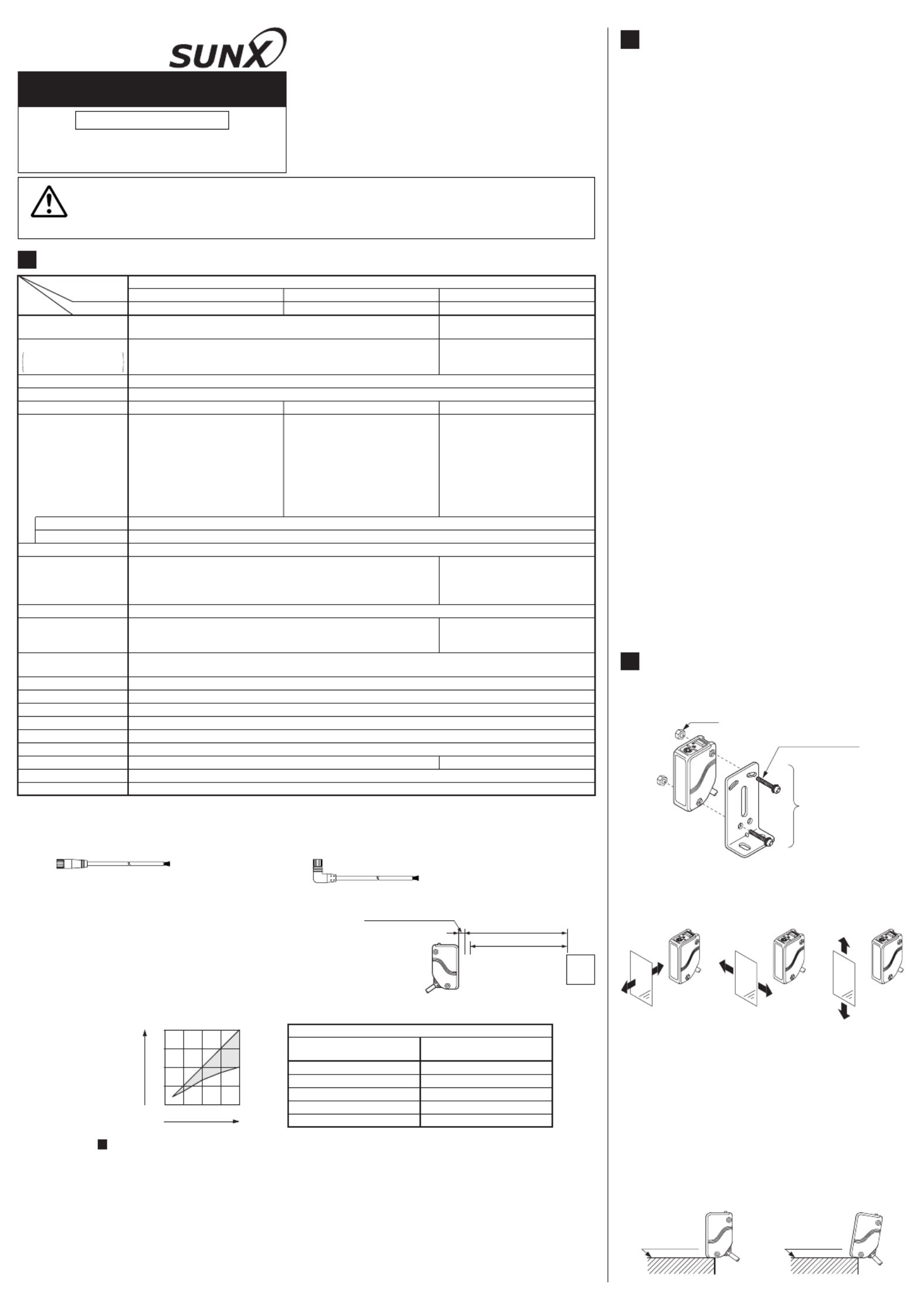
INSTRUCTION MANUAL
EQ-30 Series
Adjustable Range Reflective
Photoelectric Sensor
SPECIFICATIONS1
NPN open-collector transistor
Maximum sink current: 100mA
Applied voltage: 30V DC or less
(between output and 0V)
Residual voltage: 1V or less
(at 100mA sink current)
0.4V or less
(at 16mA sink current)
PNP open-collector transistor
Maximum source current: 100mA
Applied voltage: 30V DC or less
(between output and +V)
Residual voltage: 1V or less
(at 100mA source current)
0.4V or less
(at 16mA source current)
<Far (Main) output, Near (Sub) output>
NPN open-collector transistor
Maximum sink current: 100mA
Applied voltage: 30V DC or less
(between output and 0V)
Residual voltage: 1V or less
(at 100mA sink current)
0.4V or less
(at 16mA sink current)
90mA or less55mA or less50mA or less
0.1 to 2m
Far (Main): 0.1 to 2m
Near (Sub): 0.2 to 2m
[with Near (Sub) distance for adjuster at max.]
Output
Current consumption
Hysteresis 10% or less of operation distance
0.2 to 2m Far (Main): 0.2 to 2m
Near (Sub): Refer to diagram in (Note 3)
EQ-34
EQ-34-PN
EQ-34W
NPN output type PNP output type Two outputs type
Model No. (Note 1)
Type
Item
Adjustable range (Note 2)
Adjustable range reflective
10 to 30V DC Ripple P-P 10% or lessSupply voltage
Sensing range
with white non-glossy paper
at setting distance 2m
Red LED (lights up when the output is ON)
Far (Main) output: Red LED
[lights up when the Far (Main) output is ON]
Near (Sub) output: Red LED
[lights up when the Near (Sub) output is ON]
Operation indicator
Switchable either Detection-ON or Detection-OFF
Incorporated
Output operation
Short-circuit protection
2ms or lessResponse time
Far (Main): 2-turn mechanical ad-
juster with pointer
Near (Sub): Variable adjuster
Green LED (lights up under stable light received condition or stable dark condition) (Note 4)Stability indicator
2-turn mechanical adjuster with pointerDistance adjuster
Cable 0.3mm
23-core cabtyre cable, 2m long
0.3mm
2
4-core cabtyre cable, 2m long
2-segment photodiodeReceiving element
Adjusting screwdriver: 1pc.Accessory
Infrared LED (modulated)
Enclosure: Polyalylate and Polyethylene terephthalate, Lens: PolyalylateMaterial
IP67 (IEC)Protection
-20 to +55 (No dew condensation or icing allowed), Storage: -25 to +70Ambient temperature
35 to 85% RH, Storage: 35 to 85% RHAmbient humidity
Emitting element
Incorporated (Two units of sensors can be mounted close together.)
Automatic interference
prevention function
150g approx.Weight
Notes: 1) The model No. with suffix ' ' stands for the connector type. ( is excluded.)-J EQ-34W
(e.g.) As for the connector type of ' 'EQ-34 EQ-34-J
Use the mating cables as shown below.
CN-24L-C2 (Elbow type, 4-core, 2m)
CN-24L-C5 (Elbow type, 4-core, 5m)
CN-24-C2 (Straight type, 4-core, 2m)
CN-24-C5 (Straight type, 4-core, 5m)
4) Refer to ' ' for the details of the stability indicator.STABILITY INDICATOR
6
2)
The model No. with suffix ' ' stands for the 5m cable length type. ( is excluded.)-C5 EQ-34-PN
(e.g.) As for the 5m cable length type of EQ-34 'EQ-34-C5'
The adjustable range stands for the maximum sensing range which can
be set with the adjuster. The sensor can detect an object 0.1m, or more,
away. However, the detectable area of the Near (Sub) type of the
EQ-34W begins at 0.2m. 0.2m
0.1m
2m
Non-detectable range
Actual sensing
range of the sensor
Adjustable range
Sensing
object
3)
The Near (Sub) distance adjustable range, L , changes with the setting of the Far (Main) distance, L , as shown in the table below.2 1
EQ-34W Near (Sub) distance adjustable range
EQ-34W
Far (Main) setting distance L1Near (Sub) distance
adjustable range L
2
2m 1 to 2m
0.2m 0.2m
1.5m 0.85 to 1.5m
1m 0.65 to 1m
0.5m 0.35 to 0.5m
0 0.5 1 1.5 2
2
1.5
1
0.5
Far (Main) setting distance L1(m)
Near (Sub) distance
adjustable range
L2(m)
٨
٨
Never use this product as a sensing device for personnel protection.
In case of using sensing devices for personnel protection, use products which meet
standards, such as OSHA, ANSI or IEC etc., for personnel protection applicable in
each region or country.
WARNING
MOUNTING3
٨The tightening torque should be 0.8N㨯m or
less.
M4 nut
M4 (length 25mm)
screw with washers
Sensor
mounting
bracket
MS-EQ3-2
(Optional)
٨Care must be taken regarding the sensor
mounting direction with respect to the object's
direction of movement.
Do not make the sen-
sor detect an object
in this direction be-
cause it may cause
unstable operation.
Sensing object
No good
Sensing object
Good
Sensing object
Good
٨
٨
When detecting a specular object (aluminum or
copper foil, etc.) or an object having a glossy
surface or coating, please take care that there
are cases when the object may not be detected
due to a small change in angle, wrinkles on the
object surface, etc.
When a specular body is present below the
sensor, use the sensor by tiling it slightly up-
wards to avoid wrong operation.
Specular face
No good
Tilt
Good
Specular face
٨
٨
If a specular body is present in the background,
wrong operation may be caused due to a small
change in the angle of the background body. In
that case, install the sensor at an inclination
and confirm the operation with the actual sens-
ing object.
Some object may produce the dead zone right
in front of the sensor.
٨EQ-30 series is incorporated with automatic
interference prevention function.
Up to two sets of sensors can be installed close
together.
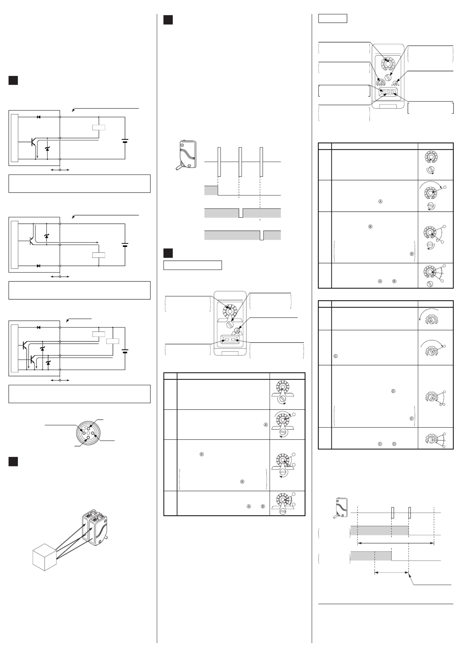
AUTOMATIC INTERFERENCE
PREVENTION FUNCTION
5
Close mounting of two sensors
٨
Since the series uses a 2-segment pho-EQ-30
todiode as its receiving element, and sensing is
done based on the difference in the incident
beam angle of the reflected beam from the
sensing object, the output and the operation in-
dicator operate according to the object distance.
Further, the stability indicator shows the margin
of the incident light intensity and not that of the
object distance.
Hence, the distance at which it lights up/off de-
pends on the object reflectivity and is not at all
related to the output operation. Do not use the
sensor when the stability indicator is off (unsta-
ble light received condition), since the sensing
will be unstable.
STABILITY INDICATOR6
Sensor
Setting distance
Sensing
object
Sensing
object
Sensing
object
Output
(operation indicator)
(In case of Detection-ON)
Stability indicator
(Black non-glossy paper)
Stability indicator
(White non-glossy paper)
Stable light
received condition
Stable dark
condition
Stable light
received condition
Stable dark
condition
Unstable light
received condition
Unstable light
received condition
ON (Lights up)
Lights up
Lights up
OFF (Turns off)
Turns off
Turns off
I/O CIRCUIT DIAGRAMS4
٨
Connector pin position of the connector type
Not connected
2
Output
㧠
+V
1
0V
3
٨NPN output type / EQ-34
Symbols...D
ZD
Tr
: Reverse supply polarity protection diode
: Surge absorption zener diode
: NPN output transistor
D
TrZD
+
-
10 to 30V
DC
Internal circuit Users' circuit
Load
(Black / 4) Output
(Blue / 3) 0V
(Bro +Vwn / 1)
Color code / Connector pin No.
of the connector type
100mA max.
Sensor circuit
Symbols...D
ZD
Tr
: Reverse supply polarity protection diode
: Surge absorption zener diode
: PNP output transistor
٨PNP output type / EQ-34-PN
(Black / 4) Output
(Blue / 3) 0V
(Brown / 1) +V
Color code / Connector pin No.
of the connector type
D
Tr
ZD+
-
10 to 30V
DC
Internal circuit Users' circuit
100mA max.
Sensor circuit
Load
٨Two outputs type / EQ-34W
Symbols...D: , Reverse supply polarity protection diode
ZD1, ZD2: Surge absorption zener diode
Tr1, Tr2: NPN output transistor
(Blue) 0V
(Brown) +V
D
Tr1
ZD1 +
-
10 to 30V
DC
Internal circuit Users' circuit
(Blac
k) Far
(Main) output
100mA max.
Tr2
ZD2
(White) Near (Sub) output
100mA max.
Color code
Sensor circuit
Load
Load
DISTANCE ADJUSTMENT7
EQ-34, EQ-34-PN
٨Adjusting procedure
Note: Use the accessory adjuster screwdriver to turn the distance
adjuster slowly. Turning with excessive force will cause dam-
age the adjuster.
Ԙ
ԙ
Ԛ
ԛ
Turn the distance adjuster fully counter-
clockwise to the minimum sensing range
position of 0.2m approx.
Place an object at the required distance
from the sensor, turn the distance adjuster
gradually clockwise, and find out point
where the sensor changes to the light re-
ceived condition.
Remove the object, turn the distance ad-
juster further counterclockwise, and find
out point where the sensor changes to
the light received condition again with only
the background.
When the sensor does not go to the light
received condition even if the adjuster is
fully turned clockwise, point is this ex-
treme point in the range.
The optimum position to stably detect ob-
jects is the center point between and .
Step
Distance adjuster
Description
N E A R
F A R
Turn fully
A
N E A R
F A R
A
N E A R
F A R
B
A
N E A R
F A R
B
Optimum
position
٨Top-view
N E A R
F A R
LD
Operation mode switch
L: Detection-ON
D: Detection-OFF
(Turn the switch fully.)
Adjuster indicator
Shows how much
the distance adjust-
er is rotated.
Distance adjuster
(2-turn)
The sensing range
increases as it is
turned clockwise.
Stability indicator (Green)
Lights up under stable
light received condition
or stable dark condition.
Operation indicator
(Red)
Lights up when the
output is ON.
PRINTED IN JAPAN
Head Office
2431-1 Ushiyama-cho, Kasugai-shi, Aichi, 486-0901, Japan
Phone: +81-(0)568-33-7211 FAX: +81-(0)568-33-2631
Overseas Sales Dept.
Phone: +81-(0)568-33-7861 FAX: +81-(0)568-33-8591
http://www.sunx.co.jp/
SUNX Limited
EQ-34W
٨Top-view
STB
NEAR
FAR
D L
SUB
MAIN
MODE
SUB MAIN
Far (Main) output
operation indicator (Red)
Lights up when the Far
(Main) output is ON.
Operation mode switch
L: Detection-ON
D: Detection-OFF
(Turn the switch fully.)
Far (Main) adjuster indicator
Shows how much the dis-
tance adjuster is rotated.
Near (Sub) distance adjuster
The sensing range increas-
es as it is turned clockwise.
Far (Main) distance
adjuster (2-turn)
The sensing range
increases as it is
turned clockwise.
Stability indicator (Green)
Lights up under stable
light received condition
or stable dark condition.
Near (Sub) output
operation indicator (Red)
Lights up when the Near
(Sub) output is ON.
٨
Adjusting procedure
Far (Main) side
Ԙ
Turn the Far (Main) distance adjuster
fully counterclockwise to the minimum
sensing range position of 0.2m approx.
Step
Distance adjuster
Description
NEAR
FAR
MAIN
Turn fully
ԙ
Ԛ
ԛ
Place an object at the far place at the re-
quired distance from the sensor, turn the
Far (Main) distance adjuster gradually clock-
wise, and find out point where the sensor
changes to the light received condition.
Remove the object, turn the Far (Main)
distance adjuster further clockwise, and
find out point where the sensor
changes to the light received condition
again with only the background.
When the sensor does not go to the
light received condition even if the ad-
juster is fully turned clockwise, point
is this extreme point in the range.
The optimum position to stably detect
objects for the Far (Main) setting is the
center point between and .
A
B
NEAR
FAR
MAIN
Optimum
position
NEAR
FAR
MAIN
A
A
B
NEAR
FAR
MAIN
Near (Sub) side
Ԙ
ԙ
Ԛ
ԛ
Turn the Near (Sub) distance adjuster
fully counterclockwise to the minimum
sensing range point.
Step
Distance adjuster
Description
SUB C
Turn fully
SUB
SUB C
D
SUB
Optimum
position
C
D
Place an object at the near position, at
the required distance from the sensor,
turn the Near (Sub) distance adjuster
gradually clockwise, and find out point
where the sensor changes to the light
received condition.
The optimum position to stably detect
objects for the Near (Sub) setting is the
center point between and .
Remove the object from the near posi-
tion, and place the object for Far (Main)
sensing at the sensing position. Turn the
Near (Sub) distance adjuster further
clockwise, and find out point where the
sensor changes to the light received con-
dition again with only the background.
When the sensor does not go to the
light received condition even if the ad-
juster is fully turned clockwise, point
is this extreme point in the range.
Notes: 1)
2)
Use the accessory adjuster screwdriver to turn the dis-
tance adjuster slowly. Turning with excessive force will
cause damage the adjuster.
The Far (Main) distance adjustment should be done
before the Near (Sub) distance adjustment. Take care
that the Near (Sub) setting distance changes with
change in the Far (Main) setting distance.
Near (Sub)
setting distance
Far (Main)
setting distance
Near object Far object
ON
OFF
ON
OFF
Near (Sub) distance
adjustable range
EQ-34W
Far (Main) distance adjustable range
(0.2 to 2m)
Near (Sub) dis-
tance adjuster set
at the maximum.
Far (Main) output
In case of
Detection-ON
Near (Sub) output
In case of
Detection-OFF
Product specificaties
| Merk: | Panasonic |
| Categorie: | Niet gecategoriseerd |
| Model: | EQ-34-PN |
Heb je hulp nodig?
Als je hulp nodig hebt met Panasonic EQ-34-PN stel dan hieronder een vraag en andere gebruikers zullen je antwoorden
Handleiding Niet gecategoriseerd Panasonic

29 Juli 2025
5 Juli 2025

23 Mei 2025
16 Mei 2025
2 Mei 2025
28 April 2025

17 April 2025

17 April 2025

17 April 2025
16 April 2025
Handleiding Niet gecategoriseerd
- Bernstein
- Glemm
- Autopilot
- JIMMY
- Catlink
- Tefal
- Maestro
- DoorBird
- Hasselblad
- Sebo
- XO
- Chauvet
- Audioengine
- MJX
- Cotech
Nieuwste handleidingen voor Niet gecategoriseerd

31 Juli 2025

31 Juli 2025

31 Juli 2025

31 Juli 2025
31 Juli 2025

31 Juli 2025

31 Juli 2025

31 Juli 2025
31 Juli 2025

31 Juli 2025