Panasonic DP-101ZL3-M-P Handleiding
Panasonic
Niet gecategoriseerd
DP-101ZL3-M-P
Bekijk gratis de handleiding van Panasonic DP-101ZL3-M-P (9 pagina’s), behorend tot de categorie Niet gecategoriseerd. Deze gids werd als nuttig beoordeeld door 16 mensen en kreeg gemiddeld 4.9 sterren uit 8.5 reviews. Heb je een vraag over Panasonic DP-101ZL3-M-P of wil je andere gebruikers van dit product iets vragen? Stel een vraag
Pagina 1/9

1
MEUML-DP100 V1.1
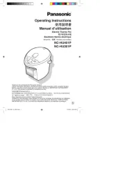
Thank you for purchasing products from Panasonic Electric Works SUNX
Co., Ltd. Please read this Instruction Manual carefully and thoroughly for
the correct and optimum use of this product. Kindly keep this manual in a
convenient place for quick reference.
This product has been developed / produced for industrial use only.
Use within the rated pressure range.
Do not apply pressure exceeding the pressure resistance value. The
diaphragm will be damaged resulting in faulty operation.
Make sure that the power supply is o while wiring.
Incorrect wiring will damage the sensor.
Verify that the supply voltage including the ripple is within the rating.
If power is supplied from a commercial switching regulator, ensure that
the frame ground (F.G.) terminal of the power supply is connected to an
actual ground.
In case noise generating equipment (switching regulator, inverter motor,
etc.) is used in the vicinity of this sensor, connect the frame ground (F.G.)
terminal of the equipment to an actual ground.
Do not use during the initial transient time (0.5s) after the power supply is
switched on.
Do not run the wires together with high-voltage lines or power lines or put
them in the same raceway. This can cause malfunction due to induction.
The specication may not be satised in a strong magnetic eld.
Avoid dust, dirt, and steam.
Take care that the sensor does not come in direct contact with water, oil,
grease, or organic solvents such as thinners, etc.
Do not insert wires, etc., into the pressure port. The diaphragm will be
damaged resulting in faulty operation.
Do not operate the keys with pointed or sharp objects.
Do not apply stress directly to the sensor cable joint by forcibly bending
or pulling.
.
Use a 12mm end wrench (14mm for DP-100-E type) when tightening a
commercial coupler to the pressure port. The tightening torque should be
9.8N·m or less (M5 female connector: 1N·m or less). The commercial
coupler or pressure port section will be damaged if the tightening torque is
excessive.
Wrap sealing tape around the coupler when connecting to prevent leaks.
INSTRUCTION MANUAL
WARNING
• Never use this product as a sensing device for personnel protection.
• In case of using sensing devices for personnel protection, use
products which meet laws and standards, such as OSHA, ANSI or
IEC etc., for personnel protection applicable in each region or
country.
• DP-100 series is designed for use with non-corrosive gas. It cannot
be used for liquid or corrosive gas.
• Japanese Measurement Laws prohibit the use of this product in
Japan.
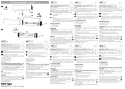
1CAUTIONS
2PART NAMES
No. Part Description
1Output 1 opera-
tion indicator
Lights up when comparative output 1 is
ON
2Output 2 / analog
voltage operation
indicator
•Standard type: lights up when
comparative output 2 is ON
•Multifunction type: lights up when
analog voltage output is ON
3Pressure unit dis-
play
Depending on the model, “MPa” or “kPa”
appears here. If you set another pressure
unit, attach the appropriate label, e.g. psi,
bar, etc.
4Main display Large 4-character LCD display.
5Sub-display Small 4-character LCD display.
6Mode selection
key
For details, see page 3, section 8,
SELECTING MODES.
7Up key Increases value being set.
8Down key Decreases value being set.
94-pin male con-
nector
See “Pin assignment, 4-pin male connec-
tor” on page 2.
0Pressure port • DP-100 type: R1/8 + M5 female screw
• DP-100-E type: G1/8 + M5 female
screw
• DP-100-M type: M5 female screw
• DP-100-N type: NPT1/8 + M5 female
screw
3PIPING
㧝
DP-100
1
0
9
876
5
4
3
2
12mm end wrench
Pressure Sensor
For use outside Japan
High-performance Digital Display
DP-100 Series

2
The sensor mounting bracket (MS-DP1-1) is available as an option.
When mounting the sensor onto the sensor mounting bracket, etc., the
tightening torque should be 0.5N·m or less.
The panel mounting bracket MS-DP1-2 (optional) and MS-DP1-4
(optional), as well as the front cover MS-DP1-3 (optional) and DPX-04
(optional) are also available.
The type of the front cover diers depending on the mounting bracket.
Use MS-DP1-3 for MS-DP1-2, and DPX-04 for MS-DP1-4.
To mount the panel mounting bracket, refer to the Instruction Manual
enclosed with MS-DP1-2 or MS-DP1-4.
Connection method
Attach the female connector of cable
CN-14A- to the 4-pin male connector.
Disconnection method
While pressing the release lever, pull out
the connector.
Pin assignment, 4-pin male connector
Notes:
When using the analog voltage output, pay careful attention to the
connected device’s input impedance.
If the cable is extended, the cable resistance will cause the voltage to
drop.
NPN output type
Standard type
Multifunction type
PNP output type
Standard type
Multifunction type
The EASY mode, hysteresis mode or window comparator mode can be
selected as the output mode for comparative output 1 and, for the standard
type DP-100, comparative output 2.
For details, see page 5, section 10, MENU SETTING MODE.
Easy mode
The comparative output is turned ON or OFF (depending on the N.O./N.C.
setting) when the threshold is reached. The tolerance of the threshold is
specied by the hysteresis setting. For details, see page 6, section 11, PRO
MODE.
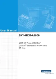
4MOUNTING
No. Part Description
1M3 (length 6mm) screws
with washers
Accessory with MS-DP1-1
2Sensor mounting bracket
(MS-DP1-1)
Optional
5WIRING
Pin no. Terminal name
1+V
2Comparative output 1
3• Standard type: Comparative
output 2
• Multifunction type: Analog
voltage output or external input
40V
6I/O CIRCUIT DIAGRAMS
1
2
CN-14A-Cغ
<Recommended product>
Contact: SPHD-001T-P0.5
Housing: PAP-04V-S
[JST Mfg. Co., Ltd.]
Release lever
C
a
bl
e w
ith
f
ema
l
e
connector
Ԙ ԙ Ԛ ԛ
㧝
7OUTPUT MODE AND OUTPUT OPERATION
Notes: • Hysteresis can be xed in 8 levels.
For details, see page 6, section 11, PRO MODE.
•P-1 is displayed for comparative output 1 and P-2 for
comparative output 2 on the sub-display.
+
_
User’s circuitInternal circuit
12 to 24V DC
±10%
(Black)
Comparative output 1
Main circuit
(White) Comparative output 2
(Blue) 0V
100mA max.
100mA max.
Load
Load
(Brown) +V
Color code of cable with connector
+
_±10%
5V
1kǡ
Main circuit
Users' circuitInternal circuit
(Black) Comparative output 1
(Blue) 0V
100mA max.
Load
(Brown) +V
Color code of cable with connector
12 to 24V DC
(White)
Analog voltage output
or external input
+
_±10%
100mA max.
Main circuit
User’s circuitInternal circuit
(Black) Comparative output 1
(White) Comparative output 2
(Blue) 0V
100mA max.
Load
Load
(Brown) +V
Color code of cable with connector
12 to 24V DC
+
_±10%
1kǡ12 to 24V D
C
Main circuit
(Black) Comparative output 1
User’s circuitInternal circuit
(Blue) 0V
100mA max.
Load
(Brown) +V
Color code of cable with connector
(White)
Analog voltage output
or external input
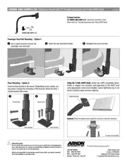
P
0
H (Hysteresis)
ON
OFF
Pressure
Comparative
output

3
Hysteresis mode
The comparative output is turned ON or OFF (depending on the N.O./N.C.
setting) when the upper or lower threshold is reached and remains ON or
OFF until the other threshold is reached.
Window comparator mode
The comparative output is turned ON or OFF (depending on the N.O./N.C.
setting) when the pressure lies between the upper or lower threshold. The
tolerance of the threshold is specified by the hysteresis setting. For details,
see page 6, section 11, PRO MODE.
DP-100 has 3 dierent modes:
RUN mode. For details, see page 3, section 9, RUN MODE.
Menu setting mode. For details, see page 5, section 10, MENU
SETTING MODE.
Pro mode. For details, see page 6, section 11, PRO MODE.
Switching modes
Press to switch between modes.
From RUN mode, press for 2s to select the menu setting mode.
From RUN mode, press for 4s to select pro mode.
To return to RUN mode, press for 2s.
In RUN mode, you can lock the keys and adjust the threshold for the param-
eters set in menu setting mode while the sensor is operating. For details,
see page 5, section 10, MENU SETTING MODE.
Threshold settings are displayed in the sub-display.
If you attempt to set threshold values that exceed the pressure range
allowed, DP-100 will alert you. UP (exceeds the upper limit) or DOWN (exceeds
the lower limit) will appear on the sub-display. DOWN will also appear if the Hi
threshold value exceeds the Lo threshold value for the hysteresis mode or
window comparator mode.
Standard type
Notes: • H (Hysteresis): 1 digit or more, 2 digits or more when psi is
selected as the pressure unit.
•Hi-1 or Lo-1 is displayed for comparative output 1 and Hi-2 or Lo-
2 for comparative output 2 on the sub-display.
Notes: • Hysteresis can be xed in 8 levels.
For details, see page 6, section 11, PRO MODE.
•Hi-1 or Lo-1 is displayed for comparative output 1 and Hi-2 or Lo-
2 for comparative output 2 on the sub-display.
8SELECTING MODES
9RUN MODE
Setting condition 1
Comparative output 1 set to: (EASY mode)EASY
Comparative output 2 set to: (OFF)OFF
0
Lo
Hi
ON
OFF
H (Hysteresis)
Pressure
Comparative
output
0
H (Hysteresis)
H (Hysteresis)
Pressure
Lo
Hi
ON
OFF
Comparative
output
MODE
MODE
MODE
MODE
Setting condition 2
Comparative output 1 set to: (EASY mode)EASY
Comparative output 2 set to: (EASY mode)EASY
Setting condition 3
Comparative output 1 set to: (EASY mode)EASY
Comparative output 2 set to: (Hysteresis mode), orHYS
WCMP (Window comparator mode)
Setting condition 4
Comparative output 1 set to: (Hysteresis mode), orHYS
WCMP (Window comparator mode)
Comparative output 2 set to: (OFF)OFF
Setting condition 5
Comparative output 1 set to: (Hysteresis mode), orHYS
WCMP (Window comparator mode)
Comparative output 2 set to: (EASY mode)EASY
Setting condition 6
Comparative output 1 set to: (Hysteresis mode), orHYS
WCMP (Window comparator mode)
Comparative output 2 set to: (Hysteresis mode), orHYS
WCMP (Window comparator mode)
MODE
Automatic
Automatic
MODE
MODE
MODE
Automatic
Automatic
Automatic
MODE
Automatic
Automatic
MODE
MODE
MODE
Automatic
Automatic
Automatic
MODE
MODE
MODE
MODE
Automatic
Automatic
Automatic
Automatic
Product specificaties
| Merk: | Panasonic |
| Categorie: | Niet gecategoriseerd |
| Model: | DP-101ZL3-M-P |
Heb je hulp nodig?
Als je hulp nodig hebt met Panasonic DP-101ZL3-M-P stel dan hieronder een vraag en andere gebruikers zullen je antwoorden
Handleiding Niet gecategoriseerd Panasonic

29 Juli 2025

5 Juli 2025

23 Mei 2025
16 Mei 2025

2 Mei 2025
28 April 2025
17 April 2025

17 April 2025

17 April 2025
16 April 2025
Handleiding Niet gecategoriseerd
- Kincrome
- LX Italia
- Meec Tools
- Hughes & Kettner
- Dunlop
- Dream Power
- Wabeco
- Brilliant
- Royale
- IBEAM
- TOOLMATE
- Gill
- Technics
- Grohe
- CFH
Nieuwste handleidingen voor Niet gecategoriseerd

31 Juli 2025

31 Juli 2025
31 Juli 2025

31 Juli 2025
31 Juli 2025
31 Juli 2025

31 Juli 2025

31 Juli 2025
31 Juli 2025
31 Juli 2025