Omnitron Systems CWDM/X Handleiding
Omnitron Systems Splitter CWDM/X
Bekijk gratis de handleiding van Omnitron Systems CWDM/X (31 pagina’s), behorend tot de categorie Splitter. Deze gids werd als nuttig beoordeeld door 97 mensen en kreeg gemiddeld 4.2 sterren uit 7 reviews. Heb je een vraag over Omnitron Systems CWDM/X of wil je andere gebruikers van dit product iets vragen? Stel een vraag
Pagina 1/31
iConverterCWDM/X 4 and 8 Channel MUX/DEMUX
USER MANUAL
Product Overview
Omnitron’s iConverter CWDM/X Coarse Wave Division
Multiplexing (CWDM) Multiplexer/Demultiplexer
(MUX/DEMUX) modules support ITU-T G.694.2
wavelengths between 1270nm to 1610nm in 20nm
increments.
The iConverter CWDM/X modules are available in 4
and 8-Channel models, supporting a variety of wavelengths and optional port
congurations. Up to 16 channels are supported by combining two 8-Channel
CWDM/X modules with a Band Splitter. For more information, access Omnitron’s
web page to view all relevant documents:
http://www.omnitron-systems.com/cwdm_multiplexers.php
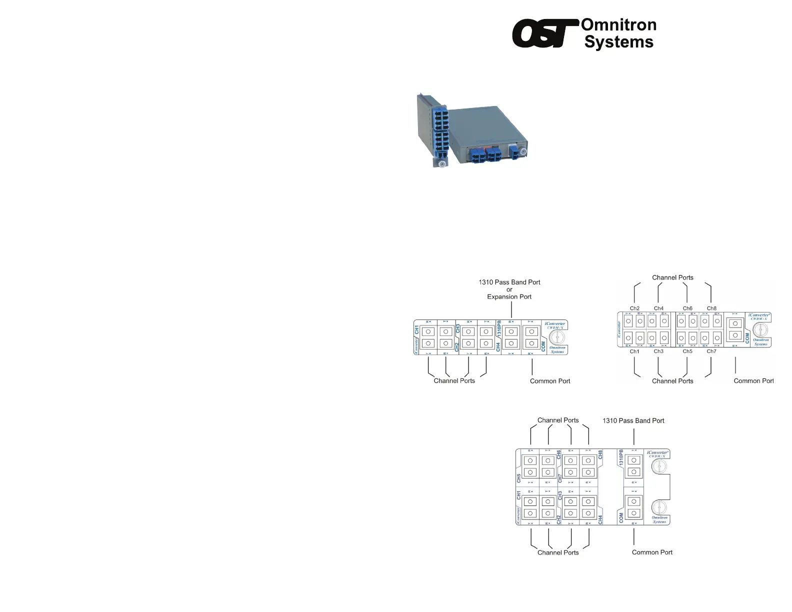
Port Denitions
4-Channel 8-Channel
Figure 1: Port Locations for 4-Channel and 8-Channel CWDM/X Module
Figure 2: Port Locations for 8-Channel Double-Wide CWDM/X Module
Design Considerations
iConverter CWDM/X modules are passive devices that require no external power.
Attenuation (signal loss) of less than 2.7dB will be realized through each port on the
module (see the CWDM/X Data Sheet for exact loss specication for each model).
Detailed calculations should be performed for each ber optic link in the network to
ensure the proper optical devices are specied with sufcient transmitter power.
When calculating optical loss, ensure that the total loss, plus a safety factor (typically
3dB) does not exceed the optical power budget. The optical power budget is the
difference between the transmitter optical output power and the receiver’s optical
sensitivity. The transmitter optical output power and receiver optical sensitivity values
can be obtained from the manufacturers of the respective equipment. Please consult
the iConverter data sheets for CWDM/X signal loss specications.
For more information, access Omnitron’s documentation download web page to
view all relevant documents:
http://www.omnitron-systems.com/downloads.php
Warranty
WARNING
The operating description in this Instruction Manual is for use by qualied personnel only. To avoid electrical shock, do not perform any
servicing of this unit other than that contained in the operating instructions, unless you are qualied and certied to do so by Omnitron
Systems Technology.
Warranty
This product is warranted to the original purchaser against defects in material and workmanship for a period of ONE YEAR from the date
of shipment. You may register your product on the Internet at http://www.omnitron-systems.com. During the warranty period, Omnitron
will, at its option, repair or replace a product which is proven to be defective.
For warranty service, the product must be sent to an Omnitron designated facility, at Buyer’s expense. Omnitron will pay the shipping
charge to return the product to Buyer’s designated US address using Omnitron’s standard shipping method.
Limitation of Warranty
The foregoing warranty shall not apply to defects resulting from improper or inadequate use and/or maintenance of the equipment by
Buyer, Buyer-supplied equipment, Buyer-supplied interfacing, unauthorized modications or tampering with equipment (including removal
of equipment cover by personnel not specically authorized and certied by Omnitron), or misuse, or operating outside the environmental
specication of the product (including but not limited to voltage, ambient temperature, radiation, unusual dust, etc.), or improper site
preparation or maintenance.
No other warranty is expressed or implied. Omnitron specically disclaims the implied warranties of merchantability and tness for any
particular purpose.
Exclusive Remedies
The remedies provided herein are the Buyer’s sole and exclusive remedies. Omnitron shall not be liable for any direct, indirect, special,
incidental, or consequential damages, whether based on contract, tort, or any legal theory.
040-08860-001D 9/13
Page 1
Omnitron Systems Technology * 38 Tesla * Irvine, CA 92618
949.250.6510 tel * 949.250.6514 fax * www.omnitron-systems.com
Product specificaties
| Merk: | Omnitron Systems |
| Categorie: | Splitter |
| Model: | CWDM/X |
Heb je hulp nodig?
Als je hulp nodig hebt met Omnitron Systems CWDM/X stel dan hieronder een vraag en andere gebruikers zullen je antwoorden
Handleiding Splitter Omnitron Systems

11 Maart 2024
Handleiding Splitter
Nieuwste handleidingen voor Splitter
29 Juni 2026
27 Juni 2026
9 Januari 2026
8 Januari 2026
4 December 2025
29 November 2025
4 November 2025
2 November 2025
1 November 2025
6 Oktober 2025