Neumann KM 64 Handleiding
Bekijk gratis de handleiding van Neumann KM 64 (16 pagina’s), behorend tot de categorie Microfoon. Deze gids werd als nuttig beoordeeld door 28 mensen en kreeg gemiddeld 4.3 sterren uit 14.5 reviews. Heb je een vraag over Neumann KM 64 of wil je andere gebruikers van dit product iets vragen? Stel een vraag
Pagina 1/16

Bedienungsanleitung
Operating Instructions
KM 100 System
georg neumann gmbh · ollenhauerstr. 98 · 13403 berlin · germany
tel +49 (0)30 / 41 77 24-0 · fax -50 · headoffice@neumann.com · www.neumann.com

2
Inhaltsverzeichnis
1. Kurzbeschreibung
2. Das Kleinmikrofon-System KM 100
2.1 Allgemeines, Beschreibung
2.2 Die verschiedenen aktiven Kapseln
2.3 Ausgangsstufe KM 100
3. Stromversorgung
3.1 Phantomspeisung
3.2 Betrieb mit Netzgeräten
3.3 Batteriespeisung
3.4 Betrieb an unsymmetrischen oder mitten-
geerdeten Eingängen
4. Technische Daten
5. Schaltbild KM 100
6. Einige Hinweise zur Pflege von Mikrofonen
7. Frequenzgänge und Polardiagramme
8. Zubehör
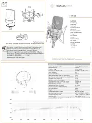
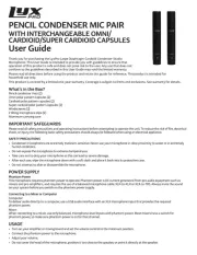
1. Kurzbeschreibung
KM 100 ist das variable Kondensator-Klein-
mikrofon-System aus der Typenreihe „fet 100®“.
Es besteht aus: aktiven Kapseln mit den Richtcha-
rakteristiken Kugel, breite Niere, Niere, Niere mit
abgesenktem Bassbereich, Hyperniere und Acht,
zwei unterschiedlichen Ausgangsstufen und um-
fangreichem Zubehör für unterschiedlichste Kap-
selmontage.
Das transformatorlose Schaltungskonzept zeichnet
sich aus durch besonders niedriges Eigengeräusch
und höchste Aussteuerbarkeit, besonders saubere,
freie und verfärbungsfreie Klangübertragung. Die
Ausgangsstufen haben einen symmetrischen,
transformatorlosen Ausgang.
Der 3-polige XLR-Stecker hat jeweils folgende
Belegung:
Pin 1: 0 V/Masse
Pin 2: Modulation (+Phase)
Pin 3: Modulation (–Phase)
Table of Contents
1. Summarized Description
2. The KM 100 Miniature Microphone System
2.1 General Information, Description
2.2 The Various Active Capsules
2.3 KM 100 Output Stage
3. Power Supply
3.1 Phantom Powering
3.2 ac Supply Operation
3.3 Battery Powering
3.4 Operation with Unbalanced or Center Tap
Grounded Inputs
4. Technical Specifications
5. Circuit Diagram KM 100
6. Some Remarks on Microphone Maintenance
7. Frequency Responses and Polar Patterns
8. Accessories
1. A Short Description
The KM 100 is the variable condenser miniature
microphone system of the “fet 100®” Series. It
consists of: active capsules with the directional
characteristics omnidirectional, wide-angle car-
dioid, cardioid, cardioid with bass roll-off, hyper-
cardioid and figure-8, two different output stages
and a comprehensive range of accessories for
widely varying methods of capsule mounting.
The main points of excellence of the transformer-
less circuit design are: remarkably low intrinsic
noise and high output capability and particularly
clean, free and colorless sound reproduction. The
output stages have a balanced, transformerless
output.
The 3-pin XLR plug connector is wired as follows:
Pin 1: 0 V/ground
Pin 2: Modulation (+phase)
Pin 3: Modulation (–phase)

4
Anwendungsempfehlungen für das Kleinmikrofon-
system KM 100 sind im Prospekt „KM 100 Appli-
cation Guide“ beschrieben.
Das KM 100-System gehört zur Typenreihe „fet
100®“, weil die Mikrofonschaltung transformator-
los arbeitet. Sie ist gekennzeichnet durch:
• besonders hohe Aussteuerbarkeit bei sehr
niedrigem Eigengeräuschpegel,
• besonders saubere, freie und verfärbungsfreie
Klangübertragung,
• besonders kompakten Aufbau, indem die ge-
samte Mikrofonschaltung als Baustein mit ca.
2 cm2 Grundfläche in Hybridbauweise zusam-
mengefasst ist.
Die Schaltung befindet sich jeweils im Gehäuse der
Mikrofonkapsel, die damit zur aktiven Kapsel
wird. Dadurch wird bei Verwendung nur der Kap-
sel, abgesetzt von der Ausgangsstufe und montiert
an einem Kabel oder auf einem Schwanenhals, die
gesamte hochwertige Mikrofonschaltung abge-
setzt. Das hat zur Folge, dass die Verwendung des
Zubehörs keinerlei Einschränkung in der Übertra-
gungsqualität bedeutet, und dass auch ein langes
Kabel zwischen aktiver Kapsel und Ausgangsstu-
fe sehr unempfindlich gegen äußere Störfelder ist.
Erst bei Kabellängen deutlich über 50 m macht
sich bei dieser Anwendung ein Abfall im oberen
Frequenzbereich bemerkbar.
Allerdings kann die Kabellänge durch starke um-
gebende Störfelder (HF, kapazitive oder indukti-
ve Einkopplungen) auf deutlich kleinere Werte be-
grenzt werden. Dann sollte nach der mindestens er-
forderlichen Kabellänge auf die Ausgangsstufe
des Systems übergegangen werden, um von dort
mit der symmetrischen Modulationsleitung (z.B.
IC 3 mt) störsicher weiterzugehen. Erst bei (Neu-
mann-) Kabellängen deutlich über 300 m macht
sich bei dieser Anwendung ein Abfall im oberen
Frequenzbereich bemerkbar.
2.2 Die verschiedenen aktiven Kapseln
Es stehen folgende sieben aktive Kapseln zur Ver-
fügung:
AK 20 ................. sw ............ Best.-Nr. 71659
Druckgradientenempfänger mit der Richtcharakte-
ristik Acht, die mit nur einer Membran realisiert
ist. Alle Schallkomponenten wirken unmittelbar
an dieser einen Membran ohne die inneren Lauf-
Application hints for using the KM 100 Miniature
microphone system are described in the catalog
“KM 100 Application Guide”.
The KM 100 system is part of the “fet 100®” Series,
the microphone circuitry being transformerless.
The system is distinguished by:
• particularly high output level with very low in-
trinsic noise,
• remarkably clean and uncolored sound repro-
duction,
• extremely compact design, the entire micro-
phone circuitry of hybrid construction is consti-
tuted by a module measuring only 2 cm2 in
area.
The circuitry is contained in the case of the micro-
phone capsule, which therefore becomes an active
capsule. Thus, if the capsule is used by itself, sep-
arately from the output stage and mounted on a
cable or gooseneck, the entire high quality micro-
phone circuitry is separated with it. The result is
that the use of the accessories entails absolutely
no impairment of the quality of reproduction and
that even a long cable connection to the active
capsule is very insensitive to external interfer-
ence fields. Only when for this application cable
lengths are well in excess of 50 m is any fall-off
in the upper frequency range noticeable.
It must be mentioned, however, that the useful ca-
ble length can be considerably reduced by strong
surrounding interference fields (RF, capacitive or
inductive coupling). In such cases, the cable length
should be kept to the bare minimum and the con-
nection to the output stage of the system should
be made, so that from this point, interference can
be eliminated with a balanced modulation lead
(e.g. IC 3 mt). It is only when (Neumann) cables are
well over 300 m that for this application any fall-
off in the upper frequency range becomes appar-
ent.
2.2 The Various Active Capsules
The following seven active capsules are avail-
able:
AK 20 ................. blk ............. Cat. No. 71659
Pressure gradient transducer with the figure-8
characteristic, realized with a single diaphragm.
All sound field components reach the diaphragm
directly without the internal path lengths in dou-
Product specificaties
| Merk: | Neumann |
| Categorie: | Microfoon |
| Model: | KM 64 |
Heb je hulp nodig?
Als je hulp nodig hebt met Neumann KM 64 stel dan hieronder een vraag en andere gebruikers zullen je antwoorden
Handleiding Microfoon Neumann

28 Februari 2025
28 Februari 2025

27 Februari 2025

2 December 2024

2 December 2024
2 December 2024

2 December 2024

16 November 2024

16 November 2024

16 November 2024
Handleiding Microfoon
- Creative
- Nedis
- Louroe Electronics
- Pixel
- Genesis
- TTQ
- VTech
- Microtech Gefell
- Miktek
- Max
- Sandberg
- Konig
- Ambient Recording
- Schoeps
- CAD Audio
Nieuwste handleidingen voor Microfoon
29 Juli 2025
29 Juli 2025
29 Juli 2025

29 Juli 2025
28 Juli 2025
28 Juli 2025

28 Juli 2025
28 Juli 2025
23 Juli 2025

22 Juli 2025