NAKS SF9-ECM Handleiding
Bekijk gratis de handleiding van NAKS SF9-ECM (7 pagina’s), behorend tot de categorie Afzuigkap. Deze gids werd als nuttig beoordeeld door 23 mensen en kreeg gemiddeld 4.3 sterren uit 12 reviews. Heb je een vraag over NAKS SF9-ECM of wil je andere gebruikers van dit product iets vragen? Stel een vraag
Pagina 1/7

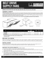
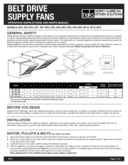
DIRECT DRIVE
SUPPLY FANS
OPERATION INSTRUCTIONS AND PARTS MANUAL
MODELS: SF5-ECM, SD7-ECM, SF8-ECM, SF9-ECM
GENERAL SAFETY
Rotating parts, (pulleys, shafts and belts) on fans should not be exposed. Where these components are not protected by ductwork, cabinets
or covers, appropriate guards should be employed to restrict exposure to rotating parts. Access doors should not be opened with the fan
operating to avoid foreign objects being drawn into the system. On initial start-up, a careful inspection should be carried out to ensure no
foreign material is present which could become airborne in the system.
Read installation and operation instructions carefully before attempting to install, operate or service NAKS SF Series Blowers. Failure to
comply with instructions could result in personal injury and/or property damage. Retain instructions for future reference.
BEFORE YOU BEGIN
Inspect unit for damage, report any shipping damage to carrier. Check all fasteners, re-tighten as required. Rotate the blower wheel by
hand to ensure free rotation. If rubbing occurs, loosen the set screw(s), re-position the wheel to the shaft center, re-tighten set screws.
INSTALLATION
Remove hood and filters from inside the cabinet. Caulk top of curb before setting unit in place. (Curb must be smaller than unit “A”
dimension). Secure unit to curb through holes located around the bottom of the unit. Tighten wheel set screw.
A
A
F
E
F
G
D
H
BOTTOM VIEW
SIZE QUANTITY
SF5-ECM 22" 24" 10 1/4" 11 7/8" 5" 3 7/8" 7 7/8" 16" 18 1/8" 19 7/8" 16" x 25" x 1" 1 21 7/8" x 21 7/8" TBA
SF7-ECM 22" 24" 11 7/8" 13 1/4" 4 7/16" 3 1/4" 6 7/8" 16" 18 1/8" 19 7/8" 16" x 25" x 1" 1 21 7/8" x 21 7/8" TBA
SF8-ECM
SF9-ECM
32" 32" 13 3/4" 15 7/8" 8 1/16" 4 1/4" 14" 25" 24 5/8" 25" 16" x 25" x 1" 2 31 7/8" x 31 7/8" TBA
*INSIDE
CABINET
UNIT WEIGHTS (LBS)
(without motors & drives)
G H L M Z
FILTERS
MODEL A B D E F
2017 Page 1 of 4
AA
B
Z
L
REMOVE CAP FOR
FILTER ACCESS
2"
Ø5/16" HOLES
FOR FASTENING
TO CURB
M
*Curb size to be smaller than inside cabinet to allow for flashing and roofing.
**Includes filter section

DIRECT DRIVE SUPPLY FANS
2017 Page 2 of 4
MESSAGE DISPLAYED...
Spd- followed by the instantaneous speed in rpm
dE- followed by S + demand in %
E1- No communications
E2- Under Voltage
Power is connected to the motor and control module through
the junction box and wiring harness provided.
Note: For 115VAC operation the blue jumper provided (taped
to wire harness) must be inserted into motor power
connector. See diagram.
CAUTION: Operating the motor at 208-230VAC with the jumper will cause significant damage to the motor.
AC SUPPLY - 115/208-230VAC
EC motors are equipped with a control module that allows for accurate
manual adjustment of motor speed. Motor speed range is from 300 to
1800 rpm or maximum rpm for that model.
The control module features a 4 digit LED display that indicates %
demand of full speed and motor speed in rpm. The display also indicates
an error code message for minor diagnostics if required.
Motor speed can be changed by adjusting the speed control pot located
on the control module. A small screwdriver can be used to make the
speed adjustment.
EC (ELECTRONICALLY CONTROLLED) MOTOR SPEED CONTROL
Note: EC motors have a soft start feature. When the power is turned on the control module gathers information from the motor then begins
the start up process. After a few seconds the motor will start to turn and reach full set speed in 10-15 seconds.
Remote Speed Control Option (please contact factory for further information)

ROOF CURB AND CAP
DUCT EXTENSION SUPPORT
(,7+(5·
25·
40” MIN
18” MIN
FIGURE 2
FIGURE 3
TER
HOOD
C
O ERV
FI
IL
T
A
BINE
T
LO
WER
BL
CA
TER CAP
FIL
INT
AKE OOD H
INST
Y
ACT
AILABLE
F
V
MOT
Y
V
Y
Y
BLOWER
MODEL IS FOR DISPLA
PURPOSE.
ACTUAL PRODUCT MA
A
AR
.
O
R & DRIVE
S
A
A
A
O
R
A
ALLED.
FIGURE 4
FIGURE 5
INSTALLATION
REQUIREMENT
Typical configuration shall be a SF air supply unit,
and a spun aluminum upblast exhaust fan. The
spun aluminum upblast exhaust fan should have a
base hinge and a grease collector.
As shown in :Figure 3
• The bottom of the exhaust fan must be
18 inches away from the roof surface.
• The outlet of the exhaust fan must be
40 inches away from the roof surface minimum.
AND
• The inlet plane must be 10 feet away from the
outlet plane horizontally.
OR
• The inlet plane must be 3 feet away from the
outlet plane vertically.
HOOD AND FILTER INSTALLATION
Attach duct section when required (by others) to the SF inlet flange. Drill 1/8” hole through duct and inlet flange and secure with metal
screws provided. Slide the hood (less filters) over the inlet flange and secure with the provided sheet metal screws.
HOOD/DUCT OVERLAP SHOULD NOT EXCEED 1”.
Remove hood cap and slide filter(s) into “U” channels located on the inner sides of the hood. Replace cap.
2017 Page 3 of 4
DIRECT DRIVE SUPPLY FANS
NFPA 96 TYPICAL
INSTALLATION
WHEEL ROTATION
SPUN ALUMINUM UPBLAST EXHAUST FAN
WITH BASE HINGE & GREASE BOX
(PURCHASED SEPARATELY)
SF SIDE INTAKE SUPPLY UNIT
INTAKE DUCT EXTENSION
(BY OTHERS)
ROOF CURB AND CAP
(BY OTHERS)
DUCT EXTENSION SUPPORT
(BY OTHERS)
Product specificaties
| Merk: | NAKS |
| Categorie: | Afzuigkap |
| Model: | SF9-ECM |
Heb je hulp nodig?
Als je hulp nodig hebt met NAKS SF9-ECM stel dan hieronder een vraag en andere gebruikers zullen je antwoorden
Handleiding Afzuigkap NAKS
26 Augustus 2025
25 Augustus 2025
25 Augustus 2025
25 Augustus 2025
25 Augustus 2025
25 Augustus 2025

10 Juni 2025

9 Juni 2025

9 Juni 2025

9 Juni 2025
Handleiding Afzuigkap
- BEKO
- Kelvinator
- Privileg
- Oranier
- Elica
- Turbo Air
- La Germania
- CENDO
- Technika
- Mepamsa
- Freggia
- Balay
- Gorenje
- Boretti
- Bora
Nieuwste handleidingen voor Afzuigkap
9 September 2025
9 September 2025
9 September 2025
9 September 2025
9 September 2025

8 September 2025
8 September 2025
8 September 2025

8 September 2025
8 September 2025