MuxLab HDMI over IP Extender Kit with PoE 500752 Handleiding
MuxLab Niet gecategoriseerd HDMI over IP Extender Kit with PoE 500752
Bekijk gratis de handleiding van MuxLab HDMI over IP Extender Kit with PoE 500752 (2 pagina’s), behorend tot de categorie Niet gecategoriseerd. Deze gids werd als nuttig beoordeeld door 60 mensen en kreeg gemiddeld 4.2 sterren uit 2 reviews. Heb je een vraag over MuxLab HDMI over IP Extender Kit with PoE 500752 of wil je andere gebruikers van dit product iets vragen? Stel een vraag
Pagina 1/2
© MuxLab Inc. 94-000748-D SE-000748-D
8495 Dalton Road, Mount Royal, Quebec, Canada. H4T 1V5
Tel: (514) 905-0588 Fax: (514) 905-0589
Toll Free (North America): (877) 689-5228
E-mail: videoease@muxlab.comURL: www.muxlab.com
Specifications
Environment
HDMI 1.3a
Devices
DVD, plasma, projectors, monitors, TV, PC, laptops, servers supporting HDMI.
Transmission
Transparent to the user
Video Bandwidth
225MHz
Signals
HDMI 1.3a protocol
Connectors
One (1) HDMI receptacle.
One (1) RJ45S for Cat 5e/6 unshielded or shielded twisted pair.
One (1) 3.5mm jacks for IR emitter/sensor.
Four (4) DIP Switches for device ID addressing.
Note: HDMI cables not included.
Maximum Distance
Based on a maximum length
of 6.6ft ( m) of HDMI cable
per end.
Cat5e/6: 330ft (100m) up to 1080P
Note: When installed in an electrically noisy environment, an STP cable must be
used. Also, cross-connection reduces the effective distance depending on the
grade of twisted cable used.
Latency
One (1) Frame
Compression
Motion JPEG
Network Bandwidth
60Mbps
Network Requirement
100BaseT for Point to Point; 1000BaseT for other configuration
IR Frequency
38 to 56KHz
RJ45 Pin Configuration
Reverse Polarity Sensitive.
Use EIA/TIA 568A or 586B
straight-through wiring.
RJ45 Link
Pin 1 (R) Pin 2 (T)
Pin 3 (R) Pin 6 (T)
Pin 4 (R) Pin 5 (T)
Pin 7 (R) Pin 8 (T)
Cable
One (1) Cat 5e/6 or better twisted pair cables required
Power Source
This device supports PoE (PD), an external power supply is not included. It is
intended to be powered via a PoE (PSE) Ethernet Switch. If required, an optional
power supply (500992) may be purchased separately.
PoE
IEEE 802.3af
Power Consumption
Transmitter: 2.9Watt Receiver: 1.8Watt
Temperature
Operating: 0° to 40°C Storage: -20° to 85°C
Humidity: Up to 95% non-condensing
Enclosure
Metal
Dimensions
3.70” x 3.68” x 0.97” (94 x 93.5 x 24.6mm)
Weight
1.1lbs (0.5kg)
Compliance
Regulatory: FCC, CE, RoHS Flammability: 94V0
Warranty
3 years
Order Information
500752 HDMI Over IP Extender Kit with PoE
500752-TX HDMI Over IP Encoder with PoE
500752-RX HDMI Over IP Decoder with PoE
Accessories
(These items are sold
separately)
500990 IR Emitter, and 500991 IR Sensor
500992 Univ. Power Supply 5VDC/1.2A US/UK/EU Blade
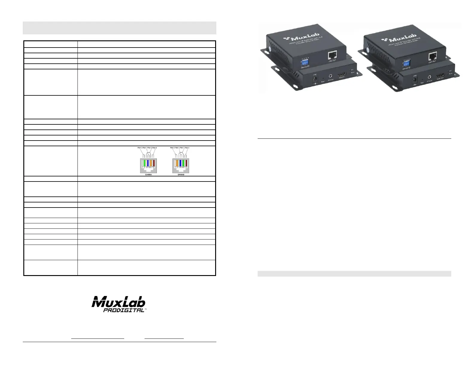
HDMI over IP Extender Kit with PoE
500752
Quick Installation Guide
Overview
The HDMI over IP Extender Kit with PoE (500752) allows HDMI equipment to be connected up to
330ft (100m) @ 1080p via one (1) Cat5e/6 unshielded twisted pair cable in a point-to-point
configuration. Point-to-multipoint and multipoint-to-multipoint is possible by connecting several
Transmitters and Receivers to the same Ethernet network. The Transmitter (500752-TX) and
Receiver (500752-RX) also support PoE (PD) if used with a PoE (PSE) Ethernet Switch. The kit
comes with one (1) Transmitter and one (1) Receiver. The IR Emitter and IR Sensor, if required,
may be purchased separately for IR based remote control applications.
For the point-to-multipoint and multipoint-to-multipoint configuration the Ethernet Switch must
have Gigabit ports and DHCP Server capability and additionally support the IGMP communication
protocol for the multipoint-to-multipoint case.MuxLab recommends using the Cisco SG300
Series Managed Switches.
The MuxLab ProDigital Network Controller (500811) is available to simplify the configuration and
utilization of the 500752 and other MuxLab IP based products via an Ethernet web interface.
Applications
Applications include commercial and residential AV systems, classroom projector systems, digital
signage, boardroom systems, collaborative PC systems, and medical information systems.
Installation
1.Identify the connectors on the Transmitter and Receiver as indicated on the product labels.
2.Verify that the distance between the HDMI Transmitter and Receiver is within MuxLab
specifications (see Specifications table for further details).
3.To install the Transmitter:
3a.Connect the Transmitter to the HDMI video source with an HDMI compliant cable.
3b.If the application is point-to-point, then connect one (1) length of Cat 5e/6 (or
higher) grade UTP cable to the RJ45 LINK connector on the Transmitter. If
transmitting over the network, use an Ethernet Switch between the TX & RX unit.
Product specificaties
| Merk: | MuxLab |
| Categorie: | Niet gecategoriseerd |
| Model: | HDMI over IP Extender Kit with PoE 500752 |
Heb je hulp nodig?
Als je hulp nodig hebt met MuxLab HDMI over IP Extender Kit with PoE 500752 stel dan hieronder een vraag en andere gebruikers zullen je antwoorden
Handleiding Niet gecategoriseerd MuxLab

12 Mei 2026
25 Maart 2026
7 December 2025
5 December 2025
3 December 2025
2 December 2025
2 December 2025
2 December 2025
1 December 2025
1 December 2025
Handleiding Niet gecategoriseerd
Nieuwste handleidingen voor Niet gecategoriseerd
8 Juni 2026
8 Juni 2026
8 Juni 2026
7 Juni 2026
7 Juni 2026
7 Juni 2026
7 Juni 2026
7 Juni 2026
6 Juni 2026
6 Juni 2026