Muller SC 58.08 pro Handleiding
Bekijk gratis de handleiding van Muller SC 58.08 pro (2 pagina’s), behorend tot de categorie Domotica. Deze gids werd als nuttig beoordeeld door 49 mensen en kreeg gemiddeld 4.5 sterren uit 3 reviews. Heb je een vraag over Muller SC 58.08 pro of wil je andere gebruikers van dit product iets vragen? Stel een vraag
Pagina 1/2
www.hugo-mueller.de BA HUpro GB -22989- 2014-07-V03 - ED - A3 Seite 1
GB
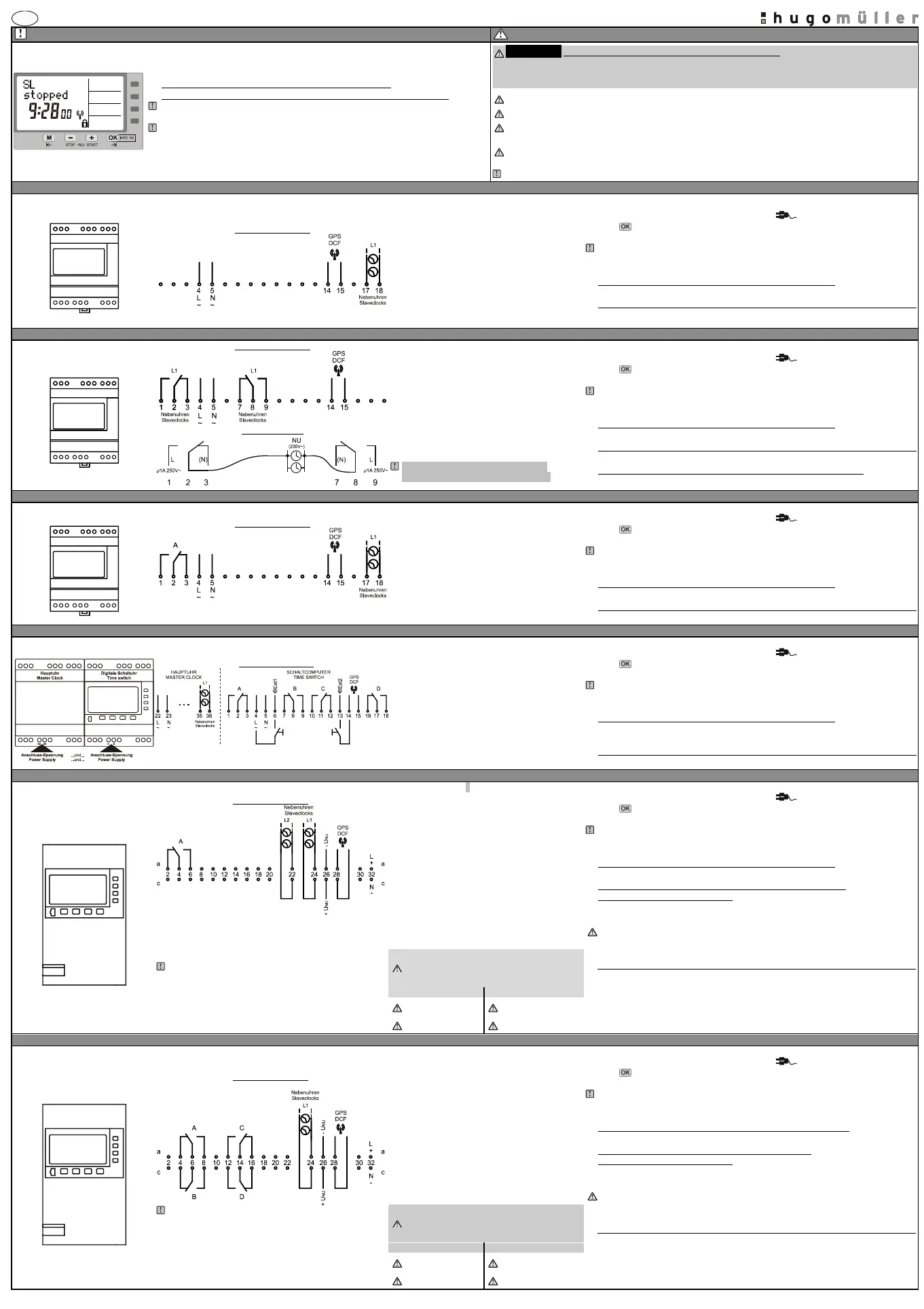
Additional instruction masterclockSite 1 / 2
PLEASE NOTE!!!
SAFETY INSTRUCTIONS
(SC 58.17 pro / SC 98.47 pro / SC 53.17 pro / SC 93.47 pro)
Please note the following for masterclock with time switch functionality:
This manual describes only masterclock features. Time switch relevant description can be
found in the standard time switch manual!
Only the connection diagram, initial operations and the safety instructions of this manual is
valid.
!!ATTENTION!!DANGER OF LIFE / RISK OF FIRE AND ELECTRIC SHOCK!!!
=> Installation and assembly of electrical equipment must be carried out only by a skilled person!!!
=> Disconnect device from power supply for wiring and installation purposes!!!
=> Defective devices have to be put out of service immediately!!!
Connect the supply voltage/frequency as stated on the product!
Warranty void if housing opened by unauthorised person!
The electronic circuit is protected against a wide range of external influences. Incorrect operating may occur if
external influences exceed certain limits!
Installation and assembly of electrical equipment must be in accordance with local building and electrical
codes!
The disposal of the device (and batteries) must be in accordance with the valid environmental and national law!
SC 58.07 pro (DIN rail mounting – master clock)
Technical dataslave-clock-line (SL)
Initial operation
SC 58.07 pro
Connection diagram
Number of lines: 1
Output voltage: 24VDC
Output current: 35mA
Conn. terminals: 17 / 18
Max. number clocks: approx. 5 slaveclocks
Output signal: Pole changing pulse
Pulse sequence:Normal operation= 1/min
During adjustment = 10/min
Pulse length: 2 sec.
(Pulse sequence/lengthadjustable)
The time switch is delivered in power back up mode (battery mode).
The display shows the power plug symbol [flashing ].
Press -button for 1 second.The display switches to automatic-mode.
(Displaying the time and the current status of the slave-clock-line (SL)).
The masterclock is already programmed with the current date and time and European
daylight savings time is activated.The slave-clock-lineis preset as follows: Minute-line
activated/ start time 12:00 / Slave-clock-line (SL)is stopped.
Power supply masterclock (See connection diagram on the left)
Connect the supply voltage/frequency as stated on the product!
Connection slave-clock-line (SL)=> master clock (See
connection diagram on the left)
Connect slave-clock-line to terminal no. 17 and 18 of the master clock.
SC 58.08 pro (DIN rail mounting – master clock)
Technical data slave-clock-line (SL)
Initial operation
SC 58.08 pro
Connection diagram
Connection sample
Number of lines: 1
Output voltage: Max. 250V~ (potential-free)
Output current: 1A
Conn. terminals: 2 / 8
Max. number clocks: Depends on the slaveclocks
Pulse sequence: Normal operation = 1/min
During adjustment = ca. 6/min
Pulse length: 8 sec.
(Pulse sequence/length adjustable)
PLEASE NOTE: The two relays are
energized alternately every minute.
The time switch is delivered inpower back up mode (battery mode).
The display shows the power plug symbol [flashing ].
Press -button for 1 second. The display switches to automatic-mode
(Displaying the time and the current status of the slave-clock-line (SL)).
The masterclock is already programmed with the current date and time and European
daylight savings time is activated. The slave-clock-line is preset as follows: Minute-line
activated / start time 12:00 / Slave-clock-line (SL)is stopped.
Power supply masterclock (See connection diagram on the left)
Connect the supply voltage/frequency as stated on the product!
Connection slave-clock-line (SL)=> master clock (See
connection diagram on the left)
Connect slave-clock-line to terminal no. 2 and 8 of the master clock.
Power supply slave-clock-line (SL) (See connection diagram on the left)
Connect power supply for clock motor(s) to terminals 1 / 9 and 3 / 7
SC 58.17 pro (DIN rail mounting – master clock with time switch functianality / weekly time switch)
Technical data slave-clock-line (SL)
Initial operation
SC 58.17 pro
Connection diagram
Number of lines: 1
Output voltage: 24VDC
Output current: 150mA
Conn. terminals: 17 / 18
Max. number clocks: approx.20 slaveclocks
Output signal: Pole changing pulse
Pulse sequence:Normal operation = 1/min
During adjustment= 10/min
Pulse length: 2 sec.
(Pulse sequence/length adjustable)
The time switch is delivered in power back up mode (battery mode).
The display shows the power plug symbol [flashing ].
Press -button for1 second. The display switches to automatic-mode
(Displaying the time and the current status of the slave-clock-line (SL)).
The master clockis already programmed with the current date and time and European
daylight savings time is activated. The slave-clock-line is preset as follows: Minute-line
activated / start time 12:00 / Slave-clock-line (SL) is stopped.
Power supply master clock (See connection diagram on the left)
Connect the supply voltage/frequency as stated on the product!
Connection slave-clock-line (SL)=> master clock (See
connection diagram on the left)
Connect slave-clock-line to terminal no. 17 and 18 of the master clock.
SC 98.47 pro(DIN rail mounting – master clockwith time switch functianality / yearly time switch)
Technical data slave-clock-line (SL)
Initial operation
SC 98.47 pro
Connection diagram
Number of lines: 1
Output voltage: 24VDC
Output current: 300mA
Conn. terminals: 35 / 36
Max. number clocks: approx. 40 slaveclocks
Output signal: Pole changing pulse
Pulse sequence:Normal operation = 1/min
During adjustment = 10/min
Pulse length: 2 sec.
(Pulse sequence/length adjustable)
The time switch is delivered in power back up mode (battery mode).
The display shows the power plug symbol [flashing ].
Press -button for 1 second. The display switches to automatic-mode
(Displaying the time and the current status of the slave-clock-line (SL)).
The master clockis already programmed with the current date and time and European
daylight savings time is activated. Theslave-clock-line is preset as follows: Minute-line
activated / start time 12:00 / Slave-clock-line (SL)is stopped.
Power supply master clock (See connection diagram on the left)
Connect the supply voltage/frequency as stated on the product!
(Master clock = terminals 22/23 / Time switch = terminals4/5).
Connection slave-clock-line (SL)=> master clock (See
connection diagram on the left)
Connect the slave-clock-line (SL)to the master clockon terminals 35 and 36
SC 53.17 pro (19”-housing –master clockwith time switch functianality / weekly time switch)
Technical data slave-clock-line (SL)
Initial operation
SC 53.17 pro
Connection diagram
SC 53.17: 2 NU-Linie
The signal output for line 1 and line 2 can be configured
independently to emit pulseseither every second or every minute!
NOTE! Power supply from a third party supplier:
The usage of a switched-mode power supply to drive the slave clock line
might disturb the reception of the FU 20.00 pro radio receiver. If the radio
receiver has no reception (the green LED on the bottom of the radio
receiver flashes rapidly or not at all)please connect GND of your
switched-mode power supply via an Y-capacitor with protective earth.
Number of lines: 2
Input USL: 24VDC (12VDC/48VDC/60VDC)
(Monitoring USL - switchable)
Output current: up to1500mA for each line
(Depends on the power supply)
Conn. terminals: See conn. diagram on the left
Max. number clocks: approx. 200 slaveclocks
(each line)
Output signal: Pole changing pulse
Pulse sequence:Normal operation = 1/min
During adjustment = 10/min
Pulse length: 2 sec.
(Pulse sequence/length adjustable)
Module: NT 73 (Power adapter slave line)
Not included indelivery!
The time switch is delivered in power back up mode (battery mode).
The display shows the power plug symbol [flashing ].
Press -button for 1 second. The display switches to automatic-mode
(Displaying the time and the current status of the slave-clock-line (SL)).
The master clockis already programmed with the current date and time and European
daylight savings time is activated. The slave-clock-line is preset as follows: Minute-line
activated / start time 12:00 / Slave-clock-line (SL) is stopped.
Power supply master clock (See connection diagram on the left)
Connect the supply voltage/frequency as stated on the product! (Terminals32a und 32c).
Connection power supply the slave-clock-line (SL)=> master clock
(See connection diagram on the left)
Depending on the specifications of the slave clocks, connect 12VDC; 24VDC; 48VDC; or
60VDC to terminals 26a and 26c.
Check polarity.
For voltages of slave clocks which differ from 24VDC, the dip switches on the PCB have to
be configured as stated within the table on the left.
Connection slave-clock-line (SL)=> master clock (See
connection diagram on the left)
Connect slave-clock-line to:
Line 1 [L1] => terminals 24a und 24c
Line 2 [L2] => terminals 22a und 22c
Table dip switches
(Power supply monitoring of the slave-clock-
line)
SL S1 S2
SL S1 S2
12VDCON ON
48VDCOFF ON
24VDCON OFF
60VDCOFF OFF
SC 93.47 pro (19”-housing –master clockwith time switch functianality / yearly time switch)
Technical data slave-clock-line (SL)
Initial operation
SC 93.47 pro
Connection diagram
NOTE! Power supply from a third party supplier:
The usage of a switched-mode power supply to drive the slave clock line
might disturb the reception of the FU 20.00 pro radio receiver. If the radio
receiver has no reception (the green LED on the bottom of the radio
receiver flashes rapidly or not at all)please connect GND of your
switched-mode power supply via an Y-capacitor with protective earth.
Number of lines: 1
Input USL: 24VDC (12VDC/48VDC/60VDC)
(Monitoring USL -switchable)
Output current:up to 1500mA
(Depends on the power supply)
Conn. terminals: See conn. diagram on the left
Max. number clocks: approx. 200 slaveclocks
Output signal: Pole changing pulse
Pulse sequence:Normal operation = 1/min
During adjustment = 10/min
Pulse length: 2 sec.
(Pulse sequence/length adjustable)
Module: NT 73 (Power adapter slave line)
Not included indelivery!
The time switch is delivered in power back up mode (battery mode).
The display shows the power plug symbol [flashing ].
Press -button for 1 second. The display switches to automatic-mode
(Displaying the time and the current status of the slave-clock-line (SL)).
The master clockis already programmed with the current date and time and European
daylight savings time is activated. The slave-clock-line is preset as follows: Minute-line
activated / start time 12:00 / Slave-clock-line (SL) is stopped.
Power supply the master clock(See connection diagram on the left)
Connect the supply voltage/frequency as stated on the product! (Terminals32a und 32c)
Connection power supply slave clockline => master clock
(See connection diagram on the left)
Depending on the specifications of the slave clocks, connect 12VDC; 24VDC; 48VDC; or
60VDC to terminals 26a and 26c.
Check polarity.
For voltages of slave clocks w
hich differ from 24VDC, the dip switches on the PCB have to
be configuredas stated within the table on the left.
Connection slave-clock-line (SL)=> master clock (See
connection diagram on the left)
Connect slave-clock-line to terminal no. 24a and 24c of the master clock.
Table dip switches
(Power supply monitoring of the slave-clock-
line)
SL S1 S2
SC S1 S2
12VDCON ON
48VDCOFF ON
24VDCON OFF
60VDCOFF OFF
Product specificaties
| Merk: | Muller |
| Categorie: | Domotica |
| Model: | SC 58.08 pro |
Heb je hulp nodig?
Als je hulp nodig hebt met Muller SC 58.08 pro stel dan hieronder een vraag en andere gebruikers zullen je antwoorden
Handleiding Domotica Muller

24 Februari 2023
24 Februari 2023
24 Februari 2023
24 Februari 2023
24 Februari 2023
24 Februari 2023
24 Februari 2023
24 Februari 2023
24 Februari 2023
24 Februari 2023
Handleiding Domotica
Nieuwste handleidingen voor Domotica
17 Oktober 2023
21 September 2023
21 September 2023
PROmax 01.162.93 - 2 Schakelaars met afstandsbediening Handleiding
1 September 2023 20 Augustus 2023
20 Augustus 2023
20 Augustus 2023
20 Augustus 2023
24 Augustus 2023
20 Augustus 2023