Microchip PIC24FJ64GA006 Handleiding
Microchip
Niet gecategoriseerd
PIC24FJ64GA006
Bekijk gratis de handleiding van Microchip PIC24FJ64GA006 (36 pagina’s), behorend tot de categorie Niet gecategoriseerd. Deze gids werd als nuttig beoordeeld door 55 mensen en kreeg gemiddeld 4.4 sterren uit 28 reviews. Heb je een vraag over Microchip PIC24FJ64GA006 of wil je andere gebruikers van dit product iets vragen? Stel een vraag
Pagina 1/36

© 2008 Microchip Technology Inc. Preliminary DS39713B-page 13-1
Parallel Master
Port (PMP)
13
Section 13. Parallel Master Port (PMP)
HIGHLIGHTS
This section of the manual contains the following major topics:
13.1 Introduction .................................................................................................................. 13-2
13.2 Module Registers......................................................................................................... 13-3
13.3 Slave Port Modes....................................................................................................... 13-11
13.4 Master Port Modes..................................................................................................... 13-16
13.5 Application Examples................................................................................................. 13-27
13.6 Operation in Power Save Modes ............................................................................... 13-30
13.7 AC Electrical Specifications ....................................................................................... 13-31
13.8 Register Maps ............................................................................................................ 13-34
13.9 Related Application Notes.......................................................................................... 13-35
13.10 Revision History ......................................................................................................... 13-36
PIC24F Family Reference Manual
DS39713B-page 13-2 Preliminary © 2008 Microchip Technology Inc.
13.1 INTRODUCTION
The Parallel Master Port (PMP) is a parallel, 8-bit I/O module specifically designed to
communicate with a wide variety of parallel devices, such as communications peripherals, LCDs,
external memory devices and microcontrollers. Because the interface to parallel peripherals
varies significantly, the PMP module is highly configurable.
Key features of the PMP module include:
• 8 Data Lines
• Up to 16 Programmable Address Lines
• Up to 2 Chip Select Lines
• Programmable Strobe Options:
- individual read and write strobes, or
- read/write strobe with enable strobe
• Address Auto-Increment/Auto-Decrement
• Programmable Address/Data Multiplexing
• Programmable Polarity on Control Signals
• Legacy Parallel Slave Port (PSP) Support
• Enhanced Parallel Slave Support:
- address support
- 4-byte deep auto-incrementing buffer
• Programmable Wait States
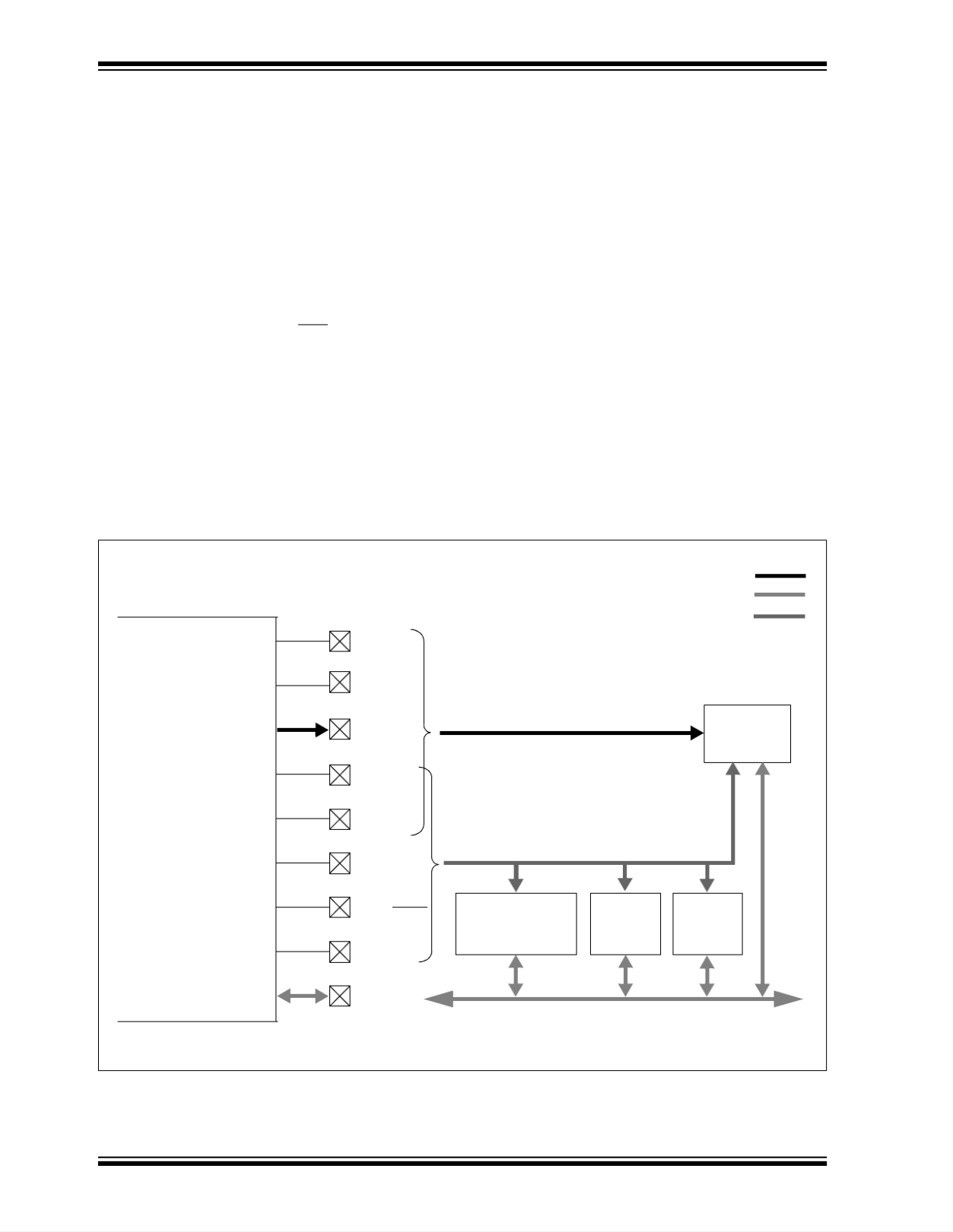
Figure 13-1: PMP Module Pinout and Connections to External Devices
PMA0
PMA14
PMA15
PMBE
PMRD
PMWR
PMD<7:0>
PMENB
PMRD/PMWR
PMCS1
PMA1
PMA<13:2>
PMALL
PMALH
PMA<7:0>
PMA<15:8>
PMCS2
EEPROM
Address Bus
Data Bus
Control Lines
PIC24F
LCD FIFO
Microcontroller
8-Bit Data (with or without multiplexed addressing)
Up to 16-Bit Address
Parallel Master Port
Buffer

© 2008 Microchip Technology Inc. Preliminary DS39713B-page 13-3
Section 13. Parallel Master Port (PMP)
Parallel Master
Port (PMP)
13
13.2 MODULE REGISTERS
The PMP module uses these Special Function Registers:
• PMCON
• PMMODE
• PMADDR/PMDOUT1
• PMDOUT2
• PMDIN1
• PMDIN2
• PMAEN
• PMSTAT
13.2.1 PMCON Register
The Parallel Master Port Control register (Register 13-1) contains the bits that control much of
the module’s basic functionality. A key bit is PMPEN, which is used to reset the module as well
as enable or disable the module. When the module is disabled, all the associated I/O pins revert
to their designated I/O function. In addition, any read or write operations, active or pending, are
stopped and the BUSY bit is cleared. The data within the module registers is retained, including
PMSTAT. Thus, the module could be disabled after a reception, and the last received data and
status would still be available for processing. When the module is enabled, all buffer control logic
is reset along with PMSTAT.
All other bits in the PMCON register control address multiplexing, enable various port control
signals and select control signal polarity. These are discussed in more detail in Section 13.4.1
“Parallel Master Port Configuration Options”.
13.2.2 PMMODE Register
The Parallel Master Port Mode register (Register 13-2) contains bits that control the operational
modes of the module. Master/Slave mode selection, as well as configuration options for both
modes, are set by this register. It also contains the universal status flag, BUSY, used in Master
modes to indicate that an operation by the module is in progress.
Details on the use of the PMMODE bits to configure PMP operation are provided in Section 13.3
“Slave Port Modes” and Section 13.4 “Master Port Modes”.
13.2.3 PMADDR/PMDOUT1 Register
Depending on the selected mode, this single register can have one of two functions. In Master
modes, the register functions as PMADDR, the Parallel Port Address register (Register 13-3). It
contains the address to which outgoing data is to be written to, as well as the chip select control
bits for addressing parallel slave devices.
In Slave modes, the register functions as PMDOUT1, and acts as a buffer for outgoing data. Its
operation is described in Section 13.3.2 “Buffered Parallel Slave Port Mode”.
13.2.4 PMDOUT2 Register
The Parallel Master Port Data Output 2 register is only used in Slave mode for buffered output
data. It is used in the same manner as PMDOUT1.
13.2.5 PMDIN1 and PMDIN2 Registers
The Parallel Master Port Data Input 1 and Data Input 2 registers are used to buffer incoming data.
PMDIN1 is used by the module in both Master and Slave modes. In Slave mode, this register is
used to hold data that is asynchronously clocked in. Its operation is described in Section 13.3.2
“Buffered Parallel Slave Port Mode”.
In Master mode, PMDIN1 is the holding register for both incoming and outgoing data. Its
operation in Master mode is described in Section 13.4.2 “Read Operation” and Section 13.4.3
“Write Operation”.
PMDIN2 is only used in Buffered Slave modes for incoming data. Its operation is similar to that
of PMDIN1 in Buffered Slave modes.
Product specificaties
| Merk: | Microchip |
| Categorie: | Niet gecategoriseerd |
| Model: | PIC24FJ64GA006 |
Heb je hulp nodig?
Als je hulp nodig hebt met Microchip PIC24FJ64GA006 stel dan hieronder een vraag en andere gebruikers zullen je antwoorden
Handleiding Niet gecategoriseerd Microchip
14 Mei 2025
6 Mei 2025

6 Mei 2025

6 Mei 2025

6 Mei 2025

6 Mei 2025

6 Mei 2025
6 Mei 2025
6 Mei 2025

6 Mei 2025
Handleiding Niet gecategoriseerd
- Desview
- Platinum
- Argon
- MIOPS
- ELMEKO
- ClimeMET
- GEV
- Allibert
- Neno
- Eura
- FitterFirst
- Sencys
- Gastronoma
- SoundTube
- Cygnett
Nieuwste handleidingen voor Niet gecategoriseerd

17 September 2025

17 September 2025

17 September 2025

17 September 2025

17 September 2025

17 September 2025

17 September 2025

17 September 2025

17 September 2025

17 September 2025