Microchip MCP3201 Handleiding
Microchip Niet gecategoriseerd MCP3201
Bekijk gratis de handleiding van Microchip MCP3201 (2 pagina’s), behorend tot de categorie Niet gecategoriseerd. Deze gids werd als nuttig beoordeeld door 62 mensen en kreeg gemiddeld 4.9 sterren uit 2 reviews. Heb je een vraag over Microchip MCP3201 of wil je andere gebruikers van dit product iets vragen? Stel een vraag
Pagina 1/2
DS21816A - Page 1
© 2003 Microchip Technology, Inc.
ANALOG DESIGN NOTE ADN001
Keeping Power Hungry Circuits Under
Thermal Control
By Bonnie C. Baker, Microchip Technology Inc.
Introduction
Projectors, large power supplies, datacom switches and routers,
pose an interesting heat dissipation problem. These applications
consume enough power to prompt a designer to cool off the
electronics with a fan. If the appropriate airflow across the
electronics is equal to or less than six to seven cubic feet per
minute (CFM), a good choice of fan would be the DC brushless
fan.
The fan speed of a DC brushless fan can be driven and controlled
by the electronics in a discrete solution, a microprocessor circuit
or a stand-alone fan controller IC. A discrete solution can be
highly customized but can be real-estate hungry. Although this
solution is a low cost alternative, it is challenging to implement
“smart” features, such as predictive fan failure or false fan failure
alarm rejection. Additionally, the hardware troubleshooting phase
for this system can be intensive as the feature set increases.
If you have a multiple fan application, the best circuit to use is
a microcontroller-based system. With the microcontroller, all
the fans and temperatures of the various environments can be
economically controlled with this one chip solution and a few
external components. The “smart” features that are difficult to
implement with discrete solutions are easily executed with the
microcontroller. The firmware of the microcontroller can be used
to set threshold temperatures and fan diagnostics for an array of
fans. Since the complexity of this system goes beyond the control
of one fan, the firmware overhead and firmware debugging can
be an issue.
For a one-fan circuit, the stand-alone fan controller IC is the
better choice. The stand-alone IC has fault detect circuitry
that can notify the system when the fan has failed, so that the
power consuming part of the system can be shutdown. The
stand-alone IC fan fault detection capability rejects glitches,
ensuring that false alarms are filtered. It can economically be
used to sense remote temperature with a NTC thermistor or
with the internal temperature sensor on-chip. As an added
benefit, the stand-alone IC can be used to detect the fan
faults of a two-wire fan, which is more economical than its
three-wire counterpart.
Regardless of the circuit option that is used, there are
three primary design issues to be considered in fan control
circuits, once the proper location of the fan is determined.
These three design issues are: fan excitation, temperature
monitoring and fan noise.
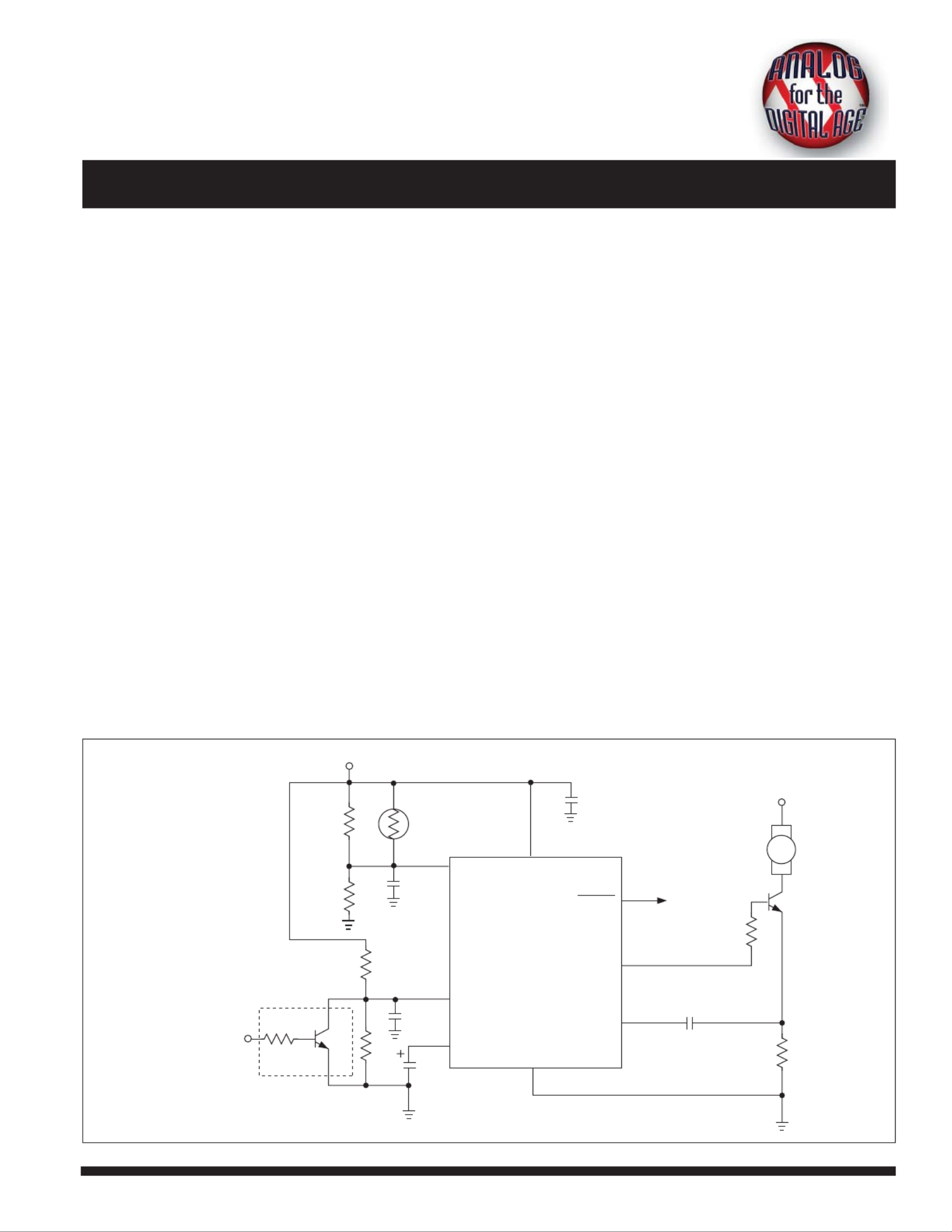
The circuit in Figure 1 illustrates how a two-wire fan can
be driven with a stand-alone IC. In this circuit, the TC647B
performs the task of varying the fan speed based on the
temperature that is sensed from the NTC thermistor. The
TC647B is also able to sense fan operation, enabling it to
indicate when a fan fault has occurred.
The speed of a brushless DC fan can be controlled by either
varying the voltage applied to it linearly or by pulse width
modulating (PWM) the voltage. The TC647B shown in Figure 1,
drives the base of transistor Q1with a PWM waveform, which
in turn drives the voltage that is applied to the fan.
FAULT
SENSE
NTC
R1
R2
R3
R4GND
Fan Fault
Shutdown
Shutdown
(Optional)
Q1
+12V
+5V
VDD
VIN
VMIN
VOUT
RBASE
RSENSE
CSENSE
CF
1 µF
CF
TC647B
Fan
CB
1 µF
CB
0.01 µF
CB
0.01 µF
18
6
7
5
4
2
3
Figure 1.A two-wire fan can easily be driven and controlled by a thermistor-connected, TC647B
Product specificaties
| Merk: | Microchip |
| Categorie: | Niet gecategoriseerd |
| Model: | MCP3201 |
Heb je hulp nodig?
Als je hulp nodig hebt met Microchip MCP3201 stel dan hieronder een vraag en andere gebruikers zullen je antwoorden
Handleiding Niet gecategoriseerd Microchip

13 Januari 2026
12 Januari 2026
12 Januari 2026
12 Januari 2026
12 Januari 2026
12 Januari 2026
6 December 2025
5 December 2025
30 November 2025
30 November 2025
Handleiding Niet gecategoriseerd
Nieuwste handleidingen voor Niet gecategoriseerd
24 Januari 2026
24 Januari 2026
24 Januari 2026
24 Januari 2026
24 Januari 2026
24 Januari 2026
24 Januari 2026
23 Januari 2026
23 Januari 2026
23 Januari 2026