Microchip MCP19122 Handleiding


Lees hieronder de 📖 handleiding in het Nederlandse voor Microchip MCP19122 (18 pagina's) in de categorie Niet gecategoriseerd. Deze handleiding was nuttig voor 42 personen en werd door 2 gebruikers gemiddeld met 4.5 sterren beoordeeld

Pagina 1/18
2015 Microchip Technology Inc. DS00001882A-page 1
AN1882
INTRODUCTION
In today's highly competitive and highly technological
world, analog signal measurements and regulation
accuracies are ever increasing. The MCP19114/5
Digitally Enhanced Power Analog Synchronous Low-Side
Pulse-Width Modulation Controller from Microchip
Technology Inc. is an analog controller capable of
implementing several switch-mode power supply
topologies. This analog device has the distinct advantage
of a built-in PIC® core microcontroller. The microcontroller
can be used to improve overall performance without the
penalties of additional cost or device area. This
application note provides several explanations complete
with firmware examples on how to improve ratiometric
and non-ratiometric analog signal measurements.
As a digitally enhanced power analog controller, the
MCP19114/5 has a built-in 10-bit Analog-to-Digital
Converter (ADC). When using the ADC in practice,
several factors will affect the accuracy of the
measurement. These factors include noise, offset
errors, DNL/INL errors and variations in the ADC
reference voltage. These error sources will have some
initial errors specified at room temperature (+25°C).
Also, the error due to temperature variation of these
parameters should not be overlooked. This application
note will provide a means of alleviating these errors.
Utilizing factory calibration is advantageous when
attempting to compensate for measurement errors.
However, reference voltage inaccuracies and
temperature drift will directly affect the ADC
measurement result and cannot be easily corrected.
The unique feature of an integral 8-bit PIC
microcontroller allows MCP19114/5 to implement
software solutions to help resolve these issues. To
address high-accuracy requirements of ADC
measurements and the temperature drift issues, two
methods are discussed in this application note. Both
methods require software coding and hardware
configurations. Examples are provided to better
understand these methods.
ASSUMPTIONS
This application note assumes the user:
is familiar with MCP19114/5 digitally enhanced
analog controllers;
has basic knowledge of Analog-to-Digital
Converters (ADC);
has working knowledge of C programming
language.
NON-RATIOMETRIC MEASUREMENT
CORRECTION
Non-ratiometric measurements are measurements
where the signal being measured is not related to the
ADC reference. The reference voltage of MCP19114/5
ADC is AVDD. Non-ratiometric measurement correction
can be achieved by measuring a signal of known
accuracy and using this measurement to correct for
other signal measurements. This method eliminates
the need to consider variations in the ADC reference
(AVDD). The MCP19114/5 internal signal VBGR (1.23V)
is factory trimmed to within 1% and has an
overtemperature tolerance of ±2.5%. This V
BGR signal
can be read internally at the MCP19114/5 ADC through
configuration of the analog test MUX (refer to registers
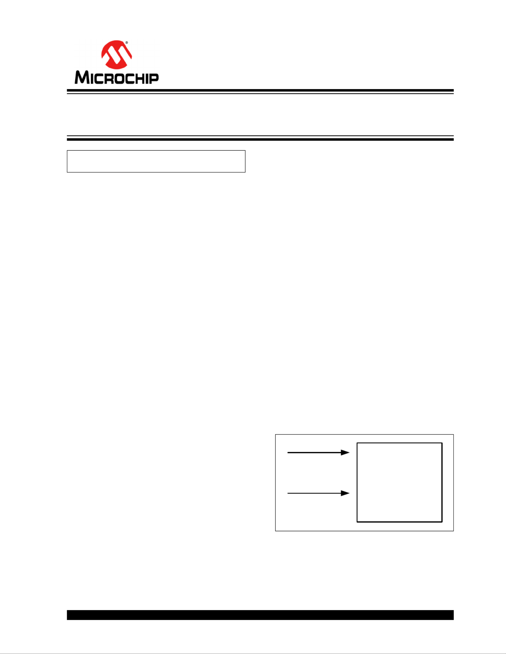
ABECON and ADCON0). Non-ratiometric correction is
a mathematical approach to eliminate the ADC
reference (AVDD) tolerance errors. This method is
presented in Figure 1.
FIGURE 1: Non-ratiometric
Measurement Correction.
Author: Yiwei Xiong
Microchip Technology Inc.
MCP19114/5
ADC
VBGR
VSIGNAL
ADC Measurement Correction and Optimization
for MCP19114/5
AN1882
DS00001882A-page 2 2015 Microchip Technology Inc.
First, use the ADC to measure VBGR. The measured
value V
ADC_BGR is calculated in Equation 1.
EQUATION 1:
Then, use the ADC to measure V
SIGNAL.
The measured value V
ADC_SIGNAL can be represented
as shown in Equation 2.
EQUATION 2:
Dividing Equation 1 by Equation 2 will cancel AVDD(V),
as shown in Equation 3.
EQUATION 3:
The accuracy impact of AVDD and the drift over
temperature is nullified in exchange for the more
precise VBGR signal accuracy over temperature. V
BGR
is factory trimmed to 1.23V ±1% (±2.5% over
temperature). VSIGNAL can be calculated as follows
from measured signals VADC_BGR
and VADC_SIGNAL by
rearranging Equation 3, as shown in Equation 4.
EQUATION 4:
If VSIGNAL threshold detection is desired, rearranging
Equation 4 and utilizing the known V
BGR value will pro-
vide a signal value in counts, as shown in Equation 5.
EQUATION 5:
In Equation 4 and Equation 5, the reference voltage
AVDD is replaced by VBGR so the measurement accuracy
will incur the tolerance of VBGR.
RATIOMETRIC MEASUREMENT
CORRECTION
Another means to reduce measurement error is to
implement ratiometric measurements. Typically, a
ratiometric ADC measurement is accomplished by
utilizing the same voltage source to excite the target
circuit as is used for the ADC reference. If a signal level
is beyond the ADC maximum measurement range, a
resistor divider is applied to lower the input signal with
a K-factor. The measured signal is proportional to the
reference voltage, thus, the accuracy of the
measurement depends on the sensor resistors instead
of the reference voltage. In the case of the
MCP19114/5, the ADC reference is powered from
AVDD (4V) and not the VDD (5V) regulator. The VDD
(5V) source is available externally to power-up target
circuits. To assist users desiring to make ratiometric
ADC measurements with the MCP19114/5, a factory-
stored ADC measurement value of VDD is available.
EQUATION 6:
FIGURE 2: Ratiometric Measurement
Correction.
VADC_BGR(counts)
VBGR V 
AVDD V 
------------------------- 1024
=
VADC_SIGNAL(counts)
VSIGNAL V 
AVDD V 
---------------------------------- 1024
=
VADC_BGR counts 
VADC_SIGNAL counts 
--------------------------------------------------------------
VBGR V 
VSIGNAL V 
----------------------------------=
VSIGNAL V  VBGR V 
VADC_SIGNAL counts 
VADC_BGR counts 
--------------------------------------------------------------=
VADC_SIGNAL counts VADC_BGR counts 
VSIGNAL V 
V
BGR V 
-----------------------------------=
KR2
R1 R2+ 
-------------------------=
R1
R2
K =
VDD
VX = (VDD × K ) MCP19114/5
ADC
R2
R1 + R2
2015 Microchip Technology Inc. DS00001882A-page 3
AN1882
Calibration Word 11 stores the internal ADC reading (in
counts) of VDD/2 or half VDD (HFVDD).This is a factory-
stored value at +25°C. This value can be used to cali-
brate ratiometric ADC measurements powered from
VDD. VDD and AVDD temperature drift track to within
1.1% over temperature.
EQUATION 7:
At x°C, the ADC measurement of signal Vx°C is shown
in Equation 8.
EQUATION 8:
VDD and AVDD voltage drift will track respectively
together over temperature. Assume at temperature
x°C, VDD and AVDD drift tracks to y%.
EQUATION 9:
Divide Equation 7 by Equation 9:
EQUATION 10:
EQUATION 11:
Once KX°C is known, the R2 value can be calculated
from Equation 6. The reference voltage AV
DD is elimi-
nated from the calculation. Since the tracking tolerance
is neglected during calculation, a tracking error will be
expected in the result. See “V
DD vs. AVDD Temperature
Drift Tracking” figure in Section 2.0 Typical Perfor-
mance Curves of the MCP19114/5 Data Sheet
(DS20005281).
VOLTAGE THRESHOLD LEVEL
CHECKING USING
NON-RATIOMETRIC MEASUREMENT
Systems requiring detection of several operation points
or thresholds can implement a comparison table. Using
Equation 5, the VADC_SIGNAL (counts) can be com-
pared to the predetermined table values to perform
system operation decisions. The example shown in
Figure 3 describes the technique.
FIGURE 3: Voltage Threshold Level
Checking Using Non-ratiometric Measurement.
In Figure 3, assume a system wants to detect three
operating thresholds of input voltage V
IN:
• VIN op1 = 8V (low)
• VIN op2 = 12V (normal)
• VIN op3 = 18V (high)
Calculate the divider K based on the hardware config-
uration. In Example 1, the divider K is set to 0.14977.
EXAMPLE 1:
Ratio Reference (R) can be defined as shown in
Equation 12
EQUATION 12:
The relationship between VSIGNAL and VIN is shown in
Equation 13.
EQUATION 13:
HFVDD counts 
VDD25
C
1
2
---
AVDD25
C
----------------------------------- 1024
=
Vx
Ccounts 
VDDx
CKx
C
AVDDx
C
------------------------------------------- 1024
=
Vx
Ccounts 
VDD25
C1 y%+ 
Kx
C
AVDD25
C1 y%+ 
--------------------------------------------------------------------------- 1024
=
VDD25
CKx
C
AVDD25
C
---------------------------------------------- 1024
=
HFVDD counts 
Vx
Ccounts 
--------------------------------------------
1
2
---
Kx
C
--------------=
Kx
C
Vx
Ccounts 
HFVDD counts 
-------------------------------------------- 1
2
---
=
R1
R2
K =
VIN
(VIN × K ) MCP19114/5
ADC
R2
R1 + R2
KR2
R1 R2+ 
------------------------- 0.14977==
R
VSIGNAL V 
VBGR
----------------------------------=
VSIGNAL V  VIN V  K
=


Product specificaties

Merk: Microchip
Categorie: Niet gecategoriseerd
Model: MCP19122

Heb je hulp nodig?

Als je hulp nodig hebt met Microchip MCP19122 stel dan hieronder een vraag en andere gebruikers zullen je antwoorden


Handleiding Niet gecategoriseerd Microchip

Handleiding Niet gecategoriseerd

Nieuwste handleidingen voor Niet gecategoriseerd