Majestic AMP4500 Handleiding
Bekijk gratis de handleiding van Majestic AMP4500 (3 pagina’s), behorend tot de categorie Receiver. Deze gids werd als nuttig beoordeeld door 63 mensen en kreeg gemiddeld 4.5 sterren uit 8 reviews. Heb je een vraag over Majestic AMP4500 of wil je andere gebruikers van dit product iets vragen? Stel een vraag
Pagina 1/3
● All chassises with stainless-steel● Intercooled Semi-conductor Technology
● PCB & Components water proof coated.● Water resistance nickel Plated 4 Gauge Powwer and
● 2 Ohm Stable MOSFET Amplifier Design Ground Connections
● Accurate Stated Amplifier Ratings● Nickel Plated Audio Input and Output Connections
● Variable Bass Boost 0 - +18dB● Efficient Heat Sink Transfer Technology
● Varable LP and HP Electronic X-OVER @ 18dB/octave● Nickel Plated RCA Output for multi-amp Installations
● Varable Subsonic Filter from 20Hz - 55Hz
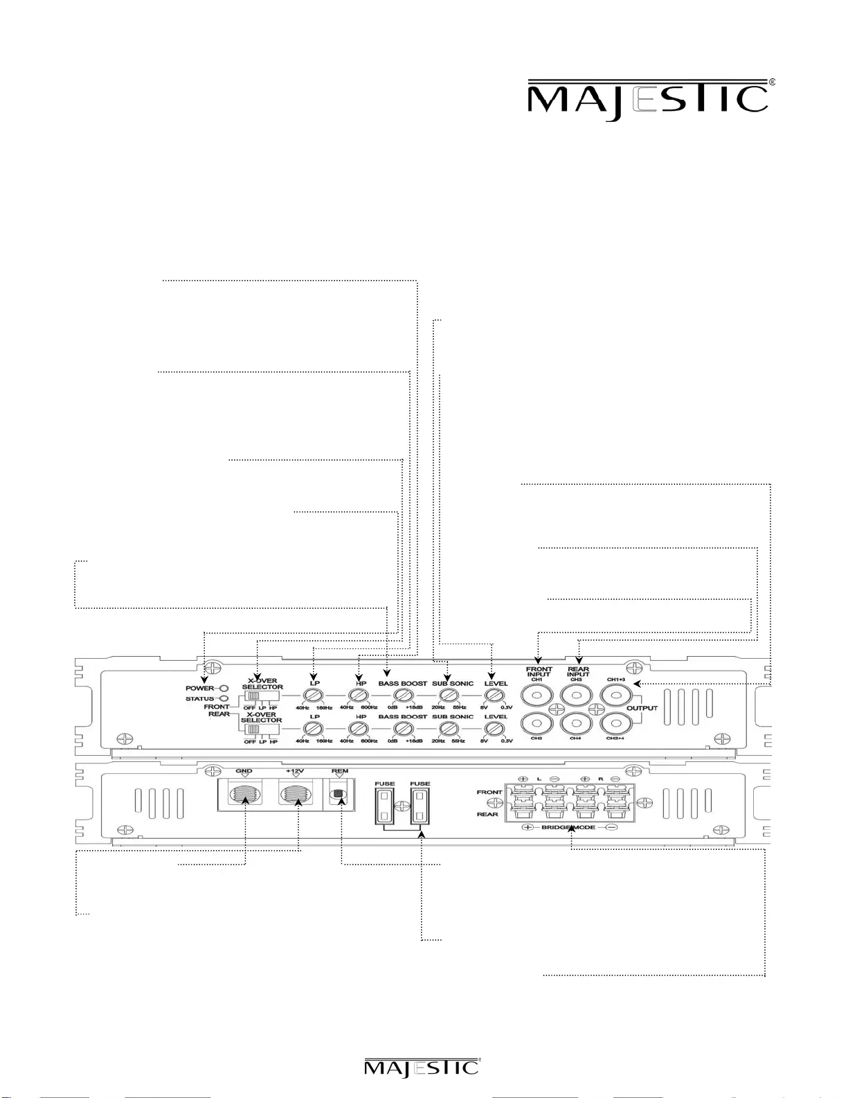
HIGH PASS
Set the crossover switch to HP and turn this control to 65Hz
or above when using speaker's smaller than 6 x 9", this feature
is designed to filter out all low bass frequencies that only SUBSONIC FILTER
SUBWOOFERS should produce. NOTE : Failure to do so could This is a variable control that filters out all Sub Bass Frequencies
result in speaker damage.below the set point at 18dB/octave.
LOW PASSLEVEL
Set the crossover switch to LP when a subwoofer is This allows level adjustment of the input signal. Use this control
connected. Ensure the crossover frequency is set at 100Hz orto correctly match the amplifier. To set this control correctly,
below, this feature is designed to filter out all mid to highturn the amplifier level to MIN and the head unit to 3/4 volume,
frequencies that only FULL RANGE speakers should produce. with the BASS and TREBLE on zero, then slowly turn up this
NOTE : Failure to do so could result in speaker damage.amplifier level control towards towards the MAX end of the
control. NOTE : If the sound becomes distorted, turn this
CROSSOVER SELECTORcontrol down.
Set the apprpriate mode of operation. The 3 positions available
are OFF, LP and HP.RCA OUTPUT
Use these RCA output connectors to connect to a secondary
POWER, STATUS AND THERMAL LED'samplifier. This output SUMMED OUTPUT connection derived from
This shows if the amplifier has been correctly powered up, if the front RCA input and the rear RCA input connectors.
any faults are present.
REAR RCA INPUT
BASS BOOSTConnect these RCA connectors to the rear LOW LEVEL output
This a variable control to increase the bass boost at 45Hz from connection from the headunit.
0 - +18dB of gain, adjust to suit.
FRONT RCA INPUT
Connect these RCA connectors to the front LOW LEVEL output
connection from the headunit.
GROUND INPUTREMOTE INPUT
Connect directly to the vehicle's chassis via a 4 gauge power cable.This terminal is for turning the amplifier on and off. This requires
NOTE : This is to be the first wire to connect when wiring up a switched postive (+)12V to power 'ON' the amplifier, this can
a amplifiers damage could result if this not done.be found on the rear of the head unit in the form of a electric
+12V INPUTantenna output, or a remote on output. If not available you
This must be connected to the vehicle battery positive(+) can wire to the ACC position on the key.
terminal via a 4 gauge power cable and with an inline fuse or FUSES
circuit breaker at the battery end. NOTE : This is to be last Please ensure correct type of fuse is fitted.
wire to connect up during installation as damage could result.
SPEAKER OUTPUT
See 4/3/2 channel installation diagrams in this manual for
correct speaker connection.
FEATURE OVERVIEW
4 Channel Marine Amplifier
AMP 4500
Product specificaties
| Merk: | Majestic |
| Categorie: | Receiver |
| Model: | AMP4500 |
Heb je hulp nodig?
Als je hulp nodig hebt met Majestic AMP4500 stel dan hieronder een vraag en andere gebruikers zullen je antwoorden
Handleiding Receiver Majestic

3 Januari 2024
3 Januari 2024
Handleiding Receiver
Nieuwste handleidingen voor Receiver
6 Juli 2026
6 Juli 2026
3 Juli 2026
2 Juli 2026
1 Juli 2026
1 Juli 2026
1 Juli 2026
1 Juli 2026
30 Juni 2026
30 Juni 2026