Legrand RT50W Handleiding
Legrand Niet gecategoriseerd RT50W
Bekijk gratis de handleiding van Legrand RT50W (2 pagina’s), behorend tot de categorie Niet gecategoriseerd. Deze gids werd als nuttig beoordeeld door 131 mensen en kreeg gemiddeld 4.4 sterren uit 8 reviews. Heb je een vraag over Legrand RT50W of wil je andere gebruikers van dit product iets vragen? Stel een vraag
Pagina 1/2
Wattstopper
®
Time Switch – 7- Button Preset
Installation Instructions • Instructions d’Installation • Instrucciones de Instalación
No: 24211 – 09/16 rev. 1
Catalog Number • Numéro de Catalogue • Número de Catálogo: RT-50
Country of Origin: Made in China • Pays d’origine: Fabriqué en Chine • País de origen: Hecho en China
SPECIFICATIONS
Voltage ..................................................120VAC, 60HZ
Load (Single Pole Circuit)
Incandescent or fluorescent lamp ....0 – 600 Watt
Fan Motor ....................................................1/6HP
Time Delay ........................1, 5, 10, 20, 30, 60 minutes
Environment .........................................Indoor use only
Operating Temperature .........32° to 131°F (0° to 55°C)
Humidity ...............................95% RH, non-condensing
Tools Needed
Insulated Screwdriver
Wire Strippers
DESCRIPTION AND OPERATION
The RT-50 is a time switch that turns OFF the connected
light or fan when the selected time expires. The light
behind the ON/OFF button illuminates while the switch
is OFF. One of the time button indicators is always lit to
indicate the last used timer.
Manual ON
Turn ON the connected light or fan by pressing the desired
time button, or the ON/OFF button. If you press the ON/
OFF button, it activates the timer that was last used.
Manual OFF
While a timer is active, you can press the ON/OFF button
to turn OFF the connected light or fan without delay.
Changing the selected time
If you decide that you need more or less time than you
originally selected, restart the time switch by pressing the
button that matches the amount of time you think you’ll need.
INSTALLATION
1. Prepare the switch box.
After the power is turned OFF at the circuit breaker box, remove the existing wall plate and mounting screws. Pull
the old switch out from the wall box.
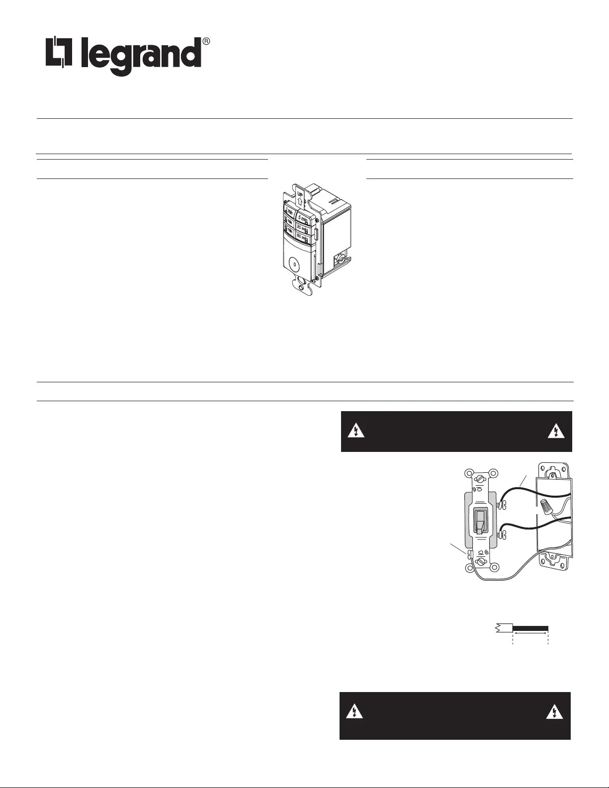
2. Identify the type of circuit.
In a Single Pole Circuit (see Fig. 1), two single wires connect to two screws on the existing
switch. A ground wire may also be present and connected to a ground terminal on the old
switch. A neutral wire should also be present in the wall box.
NOTE: If a proper ground is not available, consult with a qualified electrician before
continuing installation.
Only connect the RT-50 to a Single Pole Circuit. The RT-50 is not suitable for 3-way
switching. If the existing wiring does not match the description for a Single Pole Circuit, you
should consult with a qualified electrician.
3. Prepare the Wires.
Tag the wires currently connected to the existing switch, so that they can be identified later.
Disconnect the wires. Make sure the insulation is stripped off the wires to expose their
copper cores to the length indicated by the “Strip Gage,” in Fig. 2 (approximately 1/2 inch).
4. Wire the time switch.
Twist the existing wires together with the wire leads on the time switch as indicated in the
drawing. Cap them securely using the wire nuts provided. See Fig 3 on the next page.
• Connect the green or non-insulated (copper) GROUND wire from the circuit to the GROUND terminal
on the RT-50.
• Connect the power wire from the circuit (HOT) to the black wire on the RT-50.
• Connect the power wire to the lamp or fan (LOAD) to the red wire on the RT-50.
• Connect the NEUTRAL wires from the circuit to the white wire on the RT-50.
5. Put the RT-50 in the wall box with the time selection buttons positioned above the ON/OFF button.
Secure it to the wall box with the screws provided.
6. Install cover plates.
Install industry standard decorator wall switch cover plate (not
included).
WARNING: TURN THE POWER OFF AT THE
CIRCUIT BREAKER BEFORE WIRING.
WARNING: CONNECTING A PROPER
GROUND TO THE TIME SWITCH PROVIDES
PROTECTION AGAINST ELECTRICAL SHOCK
IN THE EVENT OF CERTAIN FAULT CONDITIONS.
Strip Gauge
1/2"
12.7 mm
Fig. 2: Wire Stripping
Ground
HOT (power from
circuit box)
LOAD
(power
to lamp)
NEUTRAL
Fig. 1: Typical Single Pole
Switch Wiring
Product specificaties
| Merk: | Legrand |
| Categorie: | Niet gecategoriseerd |
| Model: | RT50W |
Heb je hulp nodig?
Als je hulp nodig hebt met Legrand RT50W stel dan hieronder een vraag en andere gebruikers zullen je antwoorden
Handleiding Niet gecategoriseerd Legrand

25 Augustus 2025
14 Juli 2025
27 Maart 2025
27 Maart 2025
27 Maart 2025
27 Maart 2025
1 Oktober 2024
1 Oktober 2024
1 Oktober 2024
27 Augustus 2024
Handleiding Niet gecategoriseerd
Nieuwste handleidingen voor Niet gecategoriseerd
9 Maart 2026
9 Maart 2026
9 Maart 2026
9 Maart 2026
9 Maart 2026
9 Maart 2026
9 Maart 2026
9 Maart 2026
9 Maart 2026
9 Maart 2026