Lasko 3138 Handleiding
Lasko
Ventilator
3138
Bekijk gratis de handleiding van Lasko 3138 (12 pagina’s), behorend tot de categorie Ventilator. Deze gids werd als nuttig beoordeeld door 80 mensen en kreeg gemiddeld 4.9 sterren uit 40.5 reviews. Heb je een vraag over Lasko 3138 of wil je andere gebruikers van dit product iets vragen? Stel een vraag
Pagina 1/12

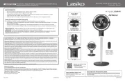
30" INDUSTRIAL GRADE OSCILLATING
PEDESTAL FAN WITH WHEELS
Model 3138
Rev. E 8/10 1 5084445
GENERAL SAFETY INFORMATION
1. Read all instructions before using Fan.
2. Make certain that the power source conforms to the electri-
cal requirements of the Fan.
3. Use this Fan only as described in this manual. Any other use not
recommended by the manufacturer may cause fire, electrical
shock, or injury to persons.
4. To reduce the risk of personal injury and electric shock, the
Fan should not be played with or placed where small children
can reach it.
5. Unplug power cord before servicing, or moving the Fan.
WARNING: DO NOT DEPEND UPON THE ON-OFF SWITCH
AS THE SOLE MEANS OF DISCONNECTING POWER WHEN
INSTALLING OR SERVICING THE FAN. ALWAYS UNPLUG THE
POWER CORD.
6. This Fan must NOT be used in potentially dangerous
locations such as flammable, explosive, chemical-laden
or wet atmospheres.
7. DO NOT use Fan in or near a window. Rain may create an
electrical hazard.
8. Completely reassemble Fan, according to instructions,
before reconnecting to power supply.
9. The power cord is equipped with a three-prong grounded
plug that must be inserted into a matching receptacle. Under
no circumstances should the grounding prong be cut off the
plug. Where a two-prong wall receptacle is encountered,
it must be replaced with a properly grounded three-prong
receptacle installed in accordance with the National Electrical
Code (NEC) and all applicable local codes and ordinances.
This work must be done only by a qualified electrician, using
copper wire only.
WARNING: USE OF A THREE-PRONG TO TWO-PRONG
ADAPTER IS NOT RECOMMENDED. IMPROPER CONNECTION
MAY CREATE THE RISK OF ELECTROCUTION. USE OF SUCH
ADAPTER IS NOT PERMITTED IN CANADA.
10. Where possible, avoid the use of extension cords. If they must
be used, minimize the risk of overheating by ensuring that they
are UL listed. Never use a single extension cord to operate
more than one Fan.
11. NEVER operate any Fan with a damaged cord or plug or after
the Fan malfunctions, has been dropped or damaged in any
manner.
12. Do not insert or allow fingers or foreign objects to enter any
ventilation or exhaust opening as it may cause an electric shock
or fire, or damage the Fan. Do not block or tamper with the Fan
in any manner while it is in operation.
13.Always place the Fan on a stable, flat, level surface when
operating, to avoid the chance of the Fan overturning. Locate
the Power Cord so the Fan or other objects are not resting on it.
Do not run cord under carpeting. Do not cover cord with throw
rugs, runners, or similar coverings. Do not route cord under
furniture or appliances. Arrange cord away from traffic area and
where it will not be tripped over.
14.This Fan is not intended for use in wet or damp locations.
Never locate a Fan where it may fall into a bathtub or other
water container.
15. Do not use Fan outdoors.
16.This Fan is not suitable for use in agricultural facilities including
areas where livestock, poultry or other animals are confined.
Please refer to National Electric Code (NEC) Article 547-7
(2008), or applicable state or local codes or standards relating
to electrical requirements for Agricultural Buildings. THIS FAN
DOES NOT MEET THE REQUIREMENTS OF NEC ARTICLE
547-7 (2008).
17.This Fan is not suitable for use in hazardous locations. Please
refer to National Electric Code (NEC) Article 500 or applicable
state or local codes or standards relating to electrical
requirements for Hazardous locations. THIS FAN DOES NOT
MEET THE REQUIREMENTS OF NEC ARTICLE 500 (2008).
WARNING: REDUCE THE RISK OF FIRE OR ELECTRIC SHOCK
– DO NOT USE THIS FAN WITH ANY SOLID STATE SPEED
CONTROL DEVICES.
CAUTION: BECAUSE OF THE SIZE AND WEIGHT OF THIS
FAN, MAKE SURE ALL PARTS ARE COMPLETELY ASSEMBLED
ACCORDING TO INSTRUCTIONS. FAILURE TO DO SO COULD
RESULT IN FAN COMING APART DURING OPERATION AND/OR
PERSONAL INJURY.
SAVE THESE INSTRUCTIONS
INCLUDED WITH THIS FAN:
(1) 3 Speed, Oscillating Motor Assembly
(1) Column Assembly
(1) Base
(1) Blade
(1) Front Grill
(1) Rear Grill
(1) Hardware Bag
(1) Motor Hardware Bag
(1) Wheel Kit Bag
(1) Instruction Sheet
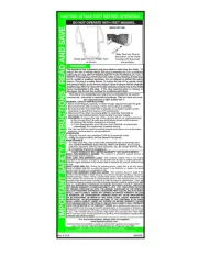
READ AND SAVE THESE INSTRUCTIONS
READ CAREFULLY BEFORE ATTEMPTING TO ASSEMBLE, INSTALL, OPERATE OR MAINTAIN THE PRODUCT DESCRIBED.
PROTECT YOURSELF AND OTHERS BY OBSERVING ALL SAFETY INFORMATION. FAILURE TO COMPLY WITH
INSTRUCTIONS COULD RESULT IN PERSONAL INJURY AND/OR PROPERTY DAMAGE!
RETAIN INSTRUCTIONS FOR FUTURE REFERENCE.

HARDWARE BAG D:
(1) Left Wheel Assembly
(1) Right Wheel Assembly
(4) Carriage Bolts (5/16-18 X 1”)
(4) Split Lockwashers (5/16”)
(4) Hex Nuts (5/16-18)
Split Lockwasher (5/16”)
Carriage Bolt
(5/16-18 X 1”)
Hex Nut (5/16-18)
Rev. E 8/10 2 5084445
HARDWARE BAG CONTENTS
MOTOR HARDWARE BAG
(1) Hex Bolt (1/2-13 X 1”)
(1) Split Lockwasher (1/2”)
(1) Hex Nut (1/2-13)
(1) Carriage Bolt (1/4-20 X 1 5/8”)
(1) Lockwasher (1/4” Internal Tooth)
(2) Flatwashers (1/4”)
(1) Adjustable Knob
(6) Hex Head Screws (10-32 X 5/16”)
(1) Pull Cord
Hex Bolt (1/2-13 X 1”)
Split Lockwasher (1/2”)
Hex Nut (1/2-13)
Hex Head Screws
(10-32 X 5/16”)
Lockwasher (1/4” Internal Tooth)
Carriage Bolt
(1/4-20 X 1 5/8”)
Flatwasher (1/4”)
Flatwasher (1/4”)
Adjustment Knob
HARDWARE BAG A:
(1) Mounting Flange
(1) Square Head Bolt (3/8-16 X 1”)
(4) Carriage Bolts (3/8-16 X 1”)
(4) Split Lockwashers (3/8”)
(4) Hex Nuts (3/8-16)
Square Head Bolt
(3/8-16 X 1”)
Carriage Bolt
(3/8-16 X 1”)
Split Lockwasher (3/8”)
Hex Nut (3/8-16)
Mounting Flange

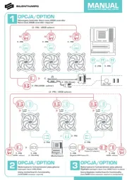
Locate Hardware Bag “D” to Assemble Wheels to
Base. (Figures 2 and 3)
1. Remove Wheel Assemblies from Hardware Bag “D”.
2. Take note that Wheel Assemblies are and RIGHT
LEFT handed. (Figure 3)
3. Place one Wheel Assembly on Base location
as shown.
4. Align two bolt holes and insert 5/16 - 18 X 1”
Long Carriage Bolt. (Figure 2)
5. Tilt Base and Secure one bolt at a time by first put-
ting on a 5/16 Split Lockwasher and then a 5/16-18
Hex Nut.
6. Repeat steps 2 thru 5 with other Wheel Assembly.
Locate Hardware Bag “A” to Assemble Base. (Figure 1)
1. Place on floor.Base
2. Fit Mounting Flange through large hole in center of Base.
3. Insert (4) through 3/8-16 X 1” Carriage Bolts Mounting
Flange Base and .
4. Tilt and secure one at a time by first Base Carriage Bolt
putting on a 3/8” Split Lockwasher and then a 3/8-16 Hex
Nut. DO NOT FULLY TIGHTEN AT THIS TIME. Repeat above
procedure with remaining Bolts.
5. GO BACK AND FULLY TIGHTEN each Hex Nut so that the
Flange Base is securely assembled to the .
6. Thread the 3/8-16 X 1” Square Head Bolt into the Mounting
Flange.
WHEELS TO BASE ASSEMBLY
BASE ASSEMBLY
Rev. E 8/10 3 5084445
Figure 1
Mounting Flange
Carriage Bolts (4)
Square Head
Bolt
Base
Hex Nut (4)
Split Lockwasher (4)
INCORRECT
CORRECT
Figure 2
Figure 3
Product specificaties
| Merk: | Lasko |
| Categorie: | Ventilator |
| Model: | 3138 |
Heb je hulp nodig?
Als je hulp nodig hebt met Lasko 3138 stel dan hieronder een vraag en andere gebruikers zullen je antwoorden
Handleiding Ventilator Lasko
14 Juni 2025

13 Juni 2025
17 Maart 2025

17 Maart 2025

17 Maart 2025
17 Maart 2025
17 Maart 2025

17 Maart 2025

17 Maart 2025

17 Maart 2025
Handleiding Ventilator
- Ardes
- GoldAir
- Elba
- Enermax
- Big Ass Fans
- Boneco
- Breville
- NEO Tools
- Zehnder
- Orion
- Clatronic
- Smartwares
- Esperanza
- Airis
- Bodin
Nieuwste handleidingen voor Ventilator
30 Juli 2025

29 Juli 2025

29 Juli 2025
29 Juli 2025

28 Juli 2025

23 Juli 2025

23 Juli 2025

22 Juli 2025

22 Juli 2025

22 Juli 2025