Lasko 3135 Handleiding
Lasko
Ventilator
3135
Bekijk gratis de handleiding van Lasko 3135 (4 pagina’s), behorend tot de categorie Ventilator. Deze gids werd als nuttig beoordeeld door 42 mensen en kreeg gemiddeld 4.8 sterren uit 21.5 reviews. Heb je een vraag over Lasko 3135 of wil je andere gebruikers van dit product iets vragen? Stel een vraag
Pagina 1/4

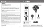
24" / 30" OSCILLATING PEDESTAL FAN
Models 3125 / 3135
Rev. D 9/07 1 5084025
Rev. D 9/07 8 5084025
GENERAL SAFETY INFORMATION
1. Read all instructions before using Fan.
2. Make certain that the power source conforms to the electrical
requirements of the Fan.
3. Use this Fan only as described in this manual. Any other use not
recommended by the manufacturer may cause re, electrical shock,
or injury to persons.
4. To reduce the risk of personal injury and electric shock, the Fan
should not be played with or placed where small children can
reach it.
5. Unplug power cord before servicing, or moving the Fan.
WARNING: DO NOT DEPEND UPON THE ON-OFF SWITCH
AS THE SOLE MEANS OF DISCONNECTING POWER WHEN
INSTALLING OR SERVICING THE FAN. ALWAYS UNPLUG THE
POWER CORD.
6. This Fan must NOT be used in potentially dangerous lo-
cations such as ammable, explosive, chemical-laden or
wet atmospheres.
7. DO NOT use Fan in or near a window. Rain may create an
electrical hazard.
8. Completely reassemble Fan, according to instructions, before
reconnecting to power supply.
9. The power cord is equipped with a three-prong grounded plug
that must be inserted into a matching receptacle. Under no
circumstances should the grounding prong be cut off the plug.
Where a two-prong wall receptacle is encountered, it must
be replaced with a properly grounded three-prong receptacle
installed in accordance with the National Electrical Code (NEC)
and all applicable local codes and ordinances. This work must
be done only by a qualied electrician, using copper wire only.
WARNING: USE OF A THREE-PRONG TO TWO-PRONG
ADAPTER IS NOT RECOMMENDED. IMPROPER CONNECTION
MAY CREATE THE RISK OF ELECTROCUTION. USE OF SUCH
ADAPTERS ARE NOT PERMITTED IN CANADA.
10.Where possible, avoid the use of extension cords. If they must be
used, minimize the risk of overheating by ensuring that they are
UL listed. Never use a single extension cord to operate more than
one Fan.
11.Do not operate any Fan with a damaged cord or plug or after the
Fan malfunctions, has been dropped or damaged in any manner.
Return Fan to authorized service facility for examination, electrical
or mechanical adjustment or repair.
12.Do not insert or allow ngers or foreign objects to enter any
ventilation or exhaust opening as it may cause an electric shock
or re, or damage the Fan. Do not block or tamper with the Fan
in any manner while it is in operation.
13.Always place the Fan on a stable, at, level surface when operating,
to avoid the chance of the Fan overturning. Locate the Power Cord
so the Fan or other objects are not resting on it. Do not run Power
Cord under carpeting. Do not cover Power Cord with throw rugs,
runners, or the like. Arrange Power Cord away from room trafc
and where it will not be tripped over.
14.This Fan is not intended for use in wet or damp locations.
Never locate a Fan where it may fall into a bathtub or other
water container.
15. Do not use Fan outdoors.
16.This Fan is not suitable for use in hazardous locations. Please
refer to National Electric Code (NEC) Article 500 or applicable
state or local codes or standards relating to electrical requirements
for Hazardous locations. THIS FAN DOES NOT MEET THE
REQUIRMENTS OF NEC ARTICLES 500 (2002).
WARNING: REDUCE THE RISK OF FIRE OR ELECTRIC SHOCK
– DO NOT USE THIS FAN WITH ANY SOLID STATE SPEED
CONTROL DEVICES.
CAUTION: BECAUSE OF THE SIZE AND WEIGHT OF THIS
FAN, MAKE SURE ALL PARTS ARE COMPLETELY ASSEMBLED
ACCORDING TO INSTRUCTIONS. FAILURE TO DO SO COULD
RESULT IN FAN COMING APART DURING OPERATION AND/OR
PERSONAL INJURY.
SAVE THESE
INSTRUCTIONS
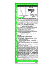
GENERAL SAFETY INFORMATION
When using electrical appliances,
basic precautions should always be followed
to reduce the risk of re, electric shock and injury to persons,
including the following:
READ AND SAVE THESE INSTRUCTIONS
READ CAREFULLY BEFORE ATTEMPTING TO ASSEMBLE, INSTALL, OPERATE OR MAINTAIN THE PRODUCT DESCRIBED.
PROTECT YOURSELF AND OTHERS BY OBSERVING ALL SAFETY INFORMATION. FAILURE TO COMPLY WITH
INSTRUCTIONS COULD RESULT IN PERSONAL INJURY AND/OR PROPERTY DAMAGE!
RETAIN INSTRUCTIONS FOR FUTURE REFERENCE.
IMPORTANT INSTRUCTIONS -
OPERATING MANUAL
INSTRUCCIONES DE TRASLADO
MANTENIMIENTO
INSTRUCCIONES DE FUNCIONAMIENTO
ADVERTENCIA: SIEMBRE DESENCHUFE EL CABLE
ANTES DE MOVER O PROPORCIONAR SERVICIO AL
VENTILADOR.
ADVERTENCIA: ¡NO SUMERJA EL VENTILADOR EN
EL AGUA!
LIMPIEZA: Use un paño suave y una solución jabonosa suave, tal
como un detergente líquido para lavar trastes. Seque todas las partes
por completo antes de reconectar el Ventilador a la fuente de poder.
ADVERTENCIA: No use gasolina, bencina, acetona,
limpiadores abrasivos, etc., puesto que dañarán el
Ventilador. NUNCA use ALCOHOL O SOLVENTES.
SERVICIO: Todos los demás servicios, con la excepción de
mantenimiento general por parte del usuario, deberán ser realizados
por un representante de servicio autorizado. Llame al 1-800-233-0268,
de Lunes a Viernes, entre las 8:00 a.m. y las 5:00 p.m. para informarse
sobre la ubicación de su centro de servicio más cercano.
LUBRICACIÓN: Los cojinetes de precisión vienen sellados de por
vida en la fábrica y no precisarán ninguna lubricación adicional.
ALMACENAMIENTO: Guarde el Ventilador con estas instrucciones
en un lugar fresco y seco.
1.
2.
3.
(Inseto A)
Del
Engranaje
De Levas
90˚
45˚
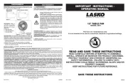
1. Enchufe el cordón en un tomacorriente de 120 V, 60 Para usar:
Hz con puesta a tierra. Seleccione la velocidad de funcionamiento
deseada usando el cordón de tirar en la parte posterior del motor.
PRECAUCIÓN: EL VENTILADOR PUEDE ENCENDERSE CUANDO
LO ENCHUFA POR PRIMERA VEZ.
Primer tirón:Alta Tercer tirón: Baja
Segundo tirón: Mediana Cuarto tirón: APAGADO
2. Mientras se sostiene Para ajustar la altura del cabezal:
rmemente la columna superior, aoje el perno del collar de la
columna (en sentido contrahorario). Eleve o baje el cabezal a la
posición deseada. Vuelva a apretar el perno FIRMEMENTE.
NOTA: Este ventilador es muy pesado. No sostener rmemente
el conjunto del cabezal mientras se ajusta la altura o el ángulo
del cabezal podría resultar en lesiones personales.
3. Empuje hacia abajo la perilla de oscilación en la caja Oscilación:
del motor para hacer que el cabezal del ventilador oscile de lado
a lado.
NOTA: EL BARCO DEL VENTILADOR CON 90º EL ÁNGULO DE
LA OSCILACIÓN, PARA OBTENER UNA OSCILACIÓN DE 45º,
CONECTE EL VÍNCULO DE OSCILACIÓN CON EL ORIFICIO MÁS
INTERNO DEL ENGRANAJE DE LEVAS.
GARANTÍA LIMITADA DE LASKO PRODUCTS, INC. (NO VÁLIDO EN MÉXICO)
QUÉ CUBRE ESTA GARANTÍAS: Este producto está garantizado contra defectos de mano de obra y/o materiales.
CUÁNTO DURA ESTA GARANTÍA: Esta garantía se extiende únicamente al comprador original del producto y dura un (1) año a partir de la fecha original
de compra o hasta que el comprador original del producto venda o transera el producto, cualesquiera de ambas que ocurriera en primer lugar.
QUÉ HARÁ LASKO: Durante el período de garantía, Lasko, a opción propia, reparará o reemplazará cualquier parte o partes que demuestren ser
defectuosas o reemplazará el producto completo por el mismo modelo u otro comparable.
QUÉ NO CUBRE ESTA GARANTÍA: Esta garantía no tiene validez si el producto fue dañado o falló debido a un accidente, manipulación u operación
inadecuadas, daño en el envío, abuso, mal uso, reparaciones no autorizadas hechas o el intento de hacerlas, o el uso del producto para servicio comercial
o no residencial. Esta garantía no cubre los costos de envío para la devolución de productos a Lasko para su reparación o reemplazo. Lasko abonará los
cargos de envío de devolución a Lasko con posterioridad a las reparaciones o el reemplazo bajo garantía
CUALESQUIERA Y TODAS LAS GARANTÍAS, EXPLÍCITAS O IMPLÍCITAS (INCLUYENDO, SIN LIMITACIÓN, CUALESQUIERA GARANTÍA IMPLÍCITA
DE COMERCIABILIDAD), DURAN UN AÑO A PARTIR DE LA FECHA ORIGINAL DE COMPRA O HASTA QUE EL COMPRADOR ORIGINAL DEL
PRODUCTO VENDA O TRANSFIERA EL PRODUCTO, CUALESQUIERA DE AMBAS QUE OCURRIERA EN PRIMER LUGAR Y EN NINGÚN CASO
LA RESPONSABILIDAD DE LASKO BAJO CUALQUIER GARANTÍA EXPLÍCITA O IMPLÍCITA INCLUIRÁ (I) DAÑOS INCIDENTALES O POR
CONSECUENCIA POR CUALQUIER CAUSA QUE FUERE, O (II) REEMPLAZO O REPARACIÓN DE CUALESQUIERA FUSIBLES HOGAREÑOS,
CORTA-CIRCUITOS O TOMACORRIENTES. INDEPENDIENTEMENTE DE CUALQUIER DECLARACIÓN CONTRARIA, EN NINGÚN CASO LA
RESPONSABILIDAD DE LASKO BAJO CUALQUIER GARANTÍA EXPLÍCITA O IMPLÍCITA PODRÁ EXCEDER EL PRECIO DE COMPRA DEL
PRODUCTO Y DICHA RESPONSABILIDAD TERMINARÁ AL VENCIMIENTO DEL PERÍODO DE GARANTÍA.
Algunos estados y provincias no permiten limitaciones sobre la duración de una garantía implícita, o sobre la exclusión o limitación de los daños incidentales
o por consecuencia, por lo tanto dichas exclusiones o limitaciones podrían no aplicarse en su caso. Esta garantía le otorga a usted derechos legales
especícos. Usted también podría tener otros derechos que varían de estado en estado y de provincia en provincia.
Se requiere prueba de compra antes que se acepte un reclamo bajo garantía.
SERVICIO AL CLIENTE:
Línea gratuita (800) 233-0268. Correo electrónico: producthelp@laskoproducts.com
Nuestro equipo de Servicio al Cliente está disponible para ayudarle con preguntas sobre productos, ubicaciones de los centros de reparación y repuestos. Se
puede comunicar con el mismo de lunes a viernes, de 8 a.m. a 5 p.m. hora del Este. Por favor tenga a manos su número de modelo, como así también el tipo
y estilo (ubicados en la parte inferior de su producto). Por favor no devuelva el producto al lugar de compra.
Customer Service Dept., 820 Lincoln Ave., West Chester, PA 19380 (Por favor no envíe el producto a este lugar) www.laskoproducts.com
LOS REPUESTOS PARA PRODUCTOS DISCONTINUADOS, OBSOLETOS Y ALGUNOS OTROS PRODUCTOS PODRÍAN NO ESTAR DISPONIBLES.
DEBIDO A RAZONES DE SEGURIDAD, MUCHOS COMPONENTES ELECTRÓNICOS Y LA MAYORÍA DE LOS COMPONENTES DE LOS CALENTADORES
NO ESTÁN DISPONIBLES AL CONSUMIDOR PARA SU INSTALACIÓN O REEMPLAZO.

Rev. D 9/07 2 5084025 Rev. D 9/07 7 5084025
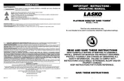
Assemble Base (Figure 1)
1. Place on oor.Base
2. Fit through large hole in center of .Mounting Flange Base
3. Insert (4) through 3/8-16 X 1" Carriage Bolts Mounting Flange
and .Base
4. Tilt and secure one at a time by rst putting Base Carriage Bolt
on a 3/8" Split Lockwasher and then a 3/8-16 Hex Nut. DO NOT
FULLY TIGHTEN AT THIS TIME. Repeat above procedure with
remaining Bolts.
5. GO BACK AND FULLY TIGHTEN each Hex Nut so that the Flange
is securely assembled to the .Base
6. Thread the into the 3/8-16 X 1" Square Head Bolt Mounting
Flange.
BASE ASSEMBLY
Locate Parts Bag “B” to Assemble Column and Motor Assembly.
1. Place at section on Upper Tube of Column Assembly next to Neck
on Motor Assembly. Align the 1/2" diameter hole in the at section
on the Upper Tube of Column Assembly with the 1/2" diameter
hole in the Motor Assembly. (Figure 2)
2. Insert the 1/2" X 1" Hex Bolt (3/4" head) through the Motor Neck,
and the Upper Tube Assembly. Place 1/2" diameter Split Lockwasher
then the 1/2" diameter Hex Nut (3/4" head) and tighten fully with a
adjustable wrench. (Figure 2)
3. From the same side of the Motor Neck,insert one 1/4-20 X 1 5/8"
Carriage Bolt through the Arc-Shaped Slot in the Motor Neck and
Hole in the Upper Pipe of Column Assembly. (Figure 2)
To Fasten: Place one 1/4" Flatwasher, one 1/4" Internal Tooth Lock-
washer, a second 1/4" Flatwasher and then tighten the Adjustable
Knob over the remaining threads.
4. Attach pull string to motor speed switch, if desired.
COLUMN AND MOTOR ASSEMBLY
Ubique las partes restantes de la Bolsa de partes “B” para Montar los Enrejados y la Hélice en el Motor.
1. Instale la Parrilla Trasera en el Motor, alineando los seis agujeros de la parrilla con los seis agujeros roscados de la brida de montaje del
motor. Instale (6) tornillos hexagonales de 10-32 x 5/16 a través de la parrilla trasera y dentro de la brida de montaje. apréte rmemente
los (6) tornillos. (Figura 4)
2. Empuje la Hélice Del Ventilador en el Eje Del Motor, centrando el Cubo orientado en sentido opuesto al motor, hasta que tope contra el eje.
(Inseto A) Alinee un perno de cabeza cuadrada con la supercie plana del eje del motor. APRÉTELO BIEN FIRME CON UNA LLAVE
DE TUERCAS AJUSTABLE. Si no se apreta rmemente el perno se puede causar daños al ventilador y/o lesiones personales.
3. Sostenga la Parrilla Delantera de modo que el nombre, en el centro, esté al derecho y horizontal. Empezando en la parte superior: Fije
la Parrilla Delantera a la Parrilla Trasera deslizando los ganchos de alambre de la Parrilla Delantera sobre el anillo exterior de la Parrilla
Trasera. Será necesario usar un destornillador en los ganchos inferiores para terminar el armado. Párese detrás (Figura 5 / Detalle A)
del ventilador. Deslice la punta plana del destornillador entre las Parrilla Delantera y Parrilla Trasera, junto a uno de los ganchos sin jar.
(Figura 5 / Detalle B) Tire del mango del destornillador hacia arriba hacia la Parrilla Trasera. Empuje el gancho de la Parrilla Delantera
para deslizarlo sobre el anillo exterior de la Parrilla Trasera. Repita el procedimiento con los ganchos restantes.
PRECAUCIÓN: NO DOBLE LOS ALAMBRES EN LAS PARRILLAS DELANTERA Y TRASERA.
1. Coloque el Conjunto de Columna y Motor sobre el piso al costado
del Conjunto de Base. Incline el Conjunto de base hacia arriba,
sobre uno de sus extremos. Levante el tubo inferior del Conjunto
de Columna e introdúzcalo dentro del Patín de Montaje. (Figura 3)
2. Apriete el Tornillo de Cabeza Cuadrada de 3/8-16 X 1" dentro
del Patín de Montaje.
3. Incline todo el conjunto hasta que quede en posición vertical.
PROCURE QUE LOS TORNILLOS INDICADOS EN LOS PASOS
CORRESPONDIENTES AL CONJUNTO DE COLUMNA Y MOTOR
ESTÉN FIJOS ANTES DE COLOCAR EL VENTILADOR EN
POSICIÓN VERTICAL.
4. Aoje el Tornillo de Cabeza Cuadrada de 3/8-16 X 1" en el Patín
de Montaje. Esto permitirá que la Columna se asiente en la parte
inferior de la Base después de colocar el Ventilador en posición
vertical.
5. Apriete el Tornillo de Cabeza Cuadrara de 3/8-16 X 1" en el Patín
de Montaje.
MONTAJE DE COLUMNA / MOTOR A LA BASE
Figure 2
Actual motor not shown for
detailed hardware view.
Figura 3
Inseto A
Figura 4
Figura 5
Detalle A
Detalle 5
MONTAJE DE ENREJADO Y HÉLICE
Figure 1
Mounting Flange
Carriage Bolts (4)
Square Head
Bolt
Base
Hex Nut (4)
Split Lockwasher (4)

Rev. D 9/07 3 5084025
Rev. D 9/07 6 5084025
Locate remaining parts from Parts Bag “B” to Assemble Grills and Blade to the Motor.
1. Install the Rear Grill onto the Motor, lining up the six holes in the grill with the six threaded holes in the motor mounting ange. Install
(6) 10-32 X 5/16" Hex Screws through the rear grill into the mounting ange. Securely tighten all (6) screws. (Figure 4)
2. Push the Fan Blade onto the Motor Shaft, centering the Hub facing away from the motor, until it stops against the shaft (Inset A) . Align
Square Head Bolt with at of the motor shaft. TIGHTEN VERY SECURELY WITH AN ADJUSTABLE WRENCH. Failure to securely
tighten the Bolt could result in damage to the Fan and/or personal injury.
3. Hold the Front Grill so that the name, in the center, is right side up and straight across. Starting at the top: Fasten Front Grill to Rear
Grill by sliding the hooked wires on the Front Grill over the outermost ring on the Rear Grill. . The bottom most (Figure 5 / Detail A)
hooks will require the use of a athead screwdriver to complete assembly. Stand behind the Fan. Slip the at of the screwdriver be-
tween the Front and Rear Grills, next to one of the unfastened hooks. (Figure 5 / Detail B) Pull screwdriver handle upwards towards
the Rear Grill. Slip the Front Grill hook over the Rear Grill outer ring with a push. Repeat procedure with remaining hooks.
CAUTION: DO NOT BEND WIRES ON THE FRONT OR THE REAR GRILLS.
COLUMN/MOTOR TO BASE ASSEMBLY
1. Rest Column and Motor Assembly on oor next to the Base
Assembly. Tilt Base Assembly up on end. Pick up lower pipe
of Column Assembly and insert into the Mounting Flange.
(Figure 3)
2. Tighten the 3/8-16 X 1” Square Head Bolt into the
Mounting Flange.
3. Tilt entire assembly to the upright position.
MAKE SURE BOLTS IN COLUMN AND MOTOR ASSEMBLY
STEPS ARE TIGHT BEFORE STANDING FAN UPRIGHT.
4. Loosen 3/8-16 X 1” Square Heat Bolt in the Mounting Flange.
This will allow the Column to settle in the bottom of the Base
after setting the Fan upright.
5. Tighten the 3/8-16 X 1” Square Head Bolt in the Mounting
Flange.
Ubique la Bolsa de Partes “B” para Montar el Conjunto de
Columna y Motor.
1. Deslice la sección plana del Tubo Superior del Conjunto de
Columna junto al Cuello del Conjunto de Motor. Alinee el oricio
de 1/2" de diámetro en la sección plana del Tubo Superior del
/Conjunto de Columna con el oricio de 1/2" de diámetro del
Conjunto de Motor. (Figura 2)
2. Introduzca el Tornillo Hexagonal de 1/2" X 1" (cabeza de 3/4") a
través del Cuello del Motor y el Conjunto del Tubo Superior. Coloque
una Arandela de Fijadora Hendida de 1/2" de diámetro y luego la
Tuerca Hexagonal de 1/2" de diámetro (cabeza de 3/4") y apriételas
completamente con una llave de tuerca ajustable. (Figura 2)
3. Desde el mismo costado del Cuello del Motor, introduzca un Tronillo
de Carruaje de 1/4-20 X 1 5/8" a través de la Ranura con Forma
de Arco en el Cuello del Motor y del Oricio en el Tubo Superior
del Conjunto de Columna. (Figura 2)
Para Fijar: Coloque una Arandela Plana de 1/4", una Arandela
Fijadora de Diente Interno, una segunda Arandela Plana, y luego
apriete la Perilla Ajustable sobre las roscas restantes.
4. Conecte la cadena de tiro al interruptor de velocidad del motor si
así lo desea.
Montar la Base. (Figura 1)
1. Coloque la sobre el piso.Base
2. Encaje el Patín de Montaje a través del oricio grande en el centro
de la .Base
3. Introduzca (4) Tornillos de Carruaje de 3/8-16 X 1" a través del
Patín de Montaje Base y la .
4. Incline la y je un Base Tornillo de Carruaje a la vez, colocando
primero una y después Arandela Fijadora Hendida de 3/8"
una Tuerca Hexagonal de 3/8-16. NO APRIETE TOTALMENTE
TODAVÍA. Repita el procedimiento anterior con los Tornillos
restantes.
5. REGRESE Y APRIETE TOTALMENTE Tuerca Hexagonal cada
de modo que el Patín Base esté jo con rmeza a la .
6. Introduzca el Tornillo de Cabeza Cuadrada de 3/8-16 X 1" dentro
del Patín de Montaje.
MONTAJE DE COLUMNA Y MOTOR
Figura 2
El motor verdadero no mostró para la
vista de hardware de detalle.
MONTAJE DE LA BASE
Figura 1
Tornillo De Cabeza
Cuadrada
Patín De Montaje
Base
Tuercas Hexagonales (4)
Arandelas Figadora
Hendida (4)
Tornillo De Carruaje (4)
Figure 3
Figure 4
Inset A
Figure 5
Detail A
Detail B
GRILL AND BLADE ASSEMBLY
Product specificaties
| Merk: | Lasko |
| Categorie: | Ventilator |
| Model: | 3135 |
| Kleur van het product: | Zwart |
| Breedte: | 838.2 mm |
| Diepte: | 774.7 mm |
| Hoogte: | 2057 mm |
| Aantal motors: | 1 |
| Aantal snelheden: | 3 |
| Plaatsing: | Vloer |
| Ventilator diameter: | 762 mm |
| Auto oscillatie: | Ja |
| Hoogte verstelbaarheidsbereik: | 1473 - 2362 mm |
| Voeten: | Ja |
Heb je hulp nodig?
Als je hulp nodig hebt met Lasko 3135 stel dan hieronder een vraag en andere gebruikers zullen je antwoorden
Handleiding Ventilator Lasko
14 Juni 2025

13 Juni 2025
17 Maart 2025

17 Maart 2025

17 Maart 2025
17 Maart 2025
17 Maart 2025

17 Maart 2025

17 Maart 2025

17 Maart 2025
Handleiding Ventilator
- Haier
- LifeSmart
- Sencor
- SHE
- Helios
- OK
- Fantini Cosmi
- Black And Decker
- Daikin
- Click
- Bestherm
- Tristar
- Guzzanti
- Orcon
- Windmill
Nieuwste handleidingen voor Ventilator
30 Juli 2025

29 Juli 2025
29 Juli 2025
29 Juli 2025
28 Juli 2025
23 Juli 2025
23 Juli 2025

22 Juli 2025

22 Juli 2025

22 Juli 2025