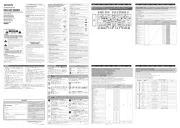
Kramer SI-1VGA Handleiding
Kramer
Controller
SI-1VGA
Bekijk gratis de handleiding van Kramer SI-1VGA (2 pagina’s), behorend tot de categorie Controller. Deze gids werd als nuttig beoordeeld door 49 mensen en kreeg gemiddeld 4.7 sterren uit 25 reviews. Heb je een vraag over Kramer SI-1VGA of wil je andere gebruikers van dit product iets vragen? Stel een vraag
Pagina 1/2

The Kramer SI 1VGA- - Step in Module
Congratulations on purchasing your Kramer SI-1VGA Step-in Module which is ideal for
boardrooms and presentation rooms.
The Kramer VGA and unbalanced stereo audio remoteSI-1VGA is a control panel that
can, for example, the Kramer fit into TBUS-10 Table Connection Box (see Figure 3) or
the The K-POD301 . Podium Table Bus SI-1VGA is used for remotely taking control of
a compatible switcher, for example, the VP-81KSi.
Figure 1 and Table 1 define the SI- 1VGA Step-in Module.
Figure SI Front Panel 1: - -1VGA Step in Module and Rear View
Table SI1: - -1VGA Step in Module Front and Rear Features
# Feature Function
1 VIDEO INPUT VGA 15-pin HD
(F) Connector
Connect to video sourcethe
2 AUDIO INPUT 3.5mm Mini
Jack
Connect to nced stereo audio source the unbala
3 STEP IN Button Press to switch the input to this remote control panel. LED lights yellow
when active
4 AUDIO OUTPUT 3.5mm Mini
Jack
Connect to unbalanced stereo audio inputthe of the switcher
5 VIDEO OUTPUT VGA 15-pin
HD (F) Connector
Connect to video inputthe of the switcher. (The cable used must connect
all pins, for example, Kramer cable CP-GMA/GMA/XL)
Figure 2 shows the wiring connections of the SI-1VGA.
Figure SI2: - 1VGA Wiring Connections
To install as illustrated in and connect the SI- 1VGA Figure 2:
Note: The eps assume that you have video (with 15 tfollowing s -pin HD (M)
connectors) and audio (with 3.5mm mini jacks) cables running from the switcher
inputs to the inside of either the TBUS-10 (see Figure 3) or the
K-POD301, depending on which you are using.
1. Connect the video cable in the TBUS- /K-10 POD301 -to the 15 pin HD VIDEO
OUTPUT connector on the rear of the SI-1VGA.
2. Connect the audio cable in the TBUS- /K-10 POD301 to the 3.5mm mini jack
AUDIO OUTPUT connector on the rear of the SI-1VGA.
3. . Insert the SI-1VGA into the required cutout of the TBUS- -10/K POD301
4. Insert the two screws to secure the module in place and tighten the screws.
5. Plug the video source (for example, a computer) into the 15-pin HD VIDEO
INPUT connector on the front panel of the SI- .1VGA
6. Plug the audio source (for example, a computer) into the 3.5mm mini jack AUDIO
INPUT connector on the front panel of SI-1VGA.
7. . Press the STEP IN button to take control of the switcher input

Figure 3 illustrates the SI-1VGA mounted in the T-BUS10.
Figure SI3: - 1VGA Mounted in the T-BUS10
Product Details
Product details of the SI- 1VGA are shown in Table 2.
Table 2: Product details1
DIMENSIONS:
- of the SI 1VGA
8.9 3.1 2.4cmcm x cm x (3.5" x 1.2" x 0.94”) W, D, H
WEIGHT: . 0.2kg ( s) approx0.44lb
ACCESSORIES: M3 x 6mm screws (2) black
1 Product details are subject to change without notice
SI- 1VGA
Step in Module-
Installation Instructions
For the latest information on our products and a list of Kramer distributors,
visit our Web site at Uhttp://www.kramerelectronics.comU
P/N:
2900- 000656
Rev:
1
Kramer Electronics, Ltd.
Web site: www.kramerelectronics.com
E-mail: info@kramerel.com
P/N: 2900-000656 1 REV
Product specificaties
| Merk: | Kramer |
| Categorie: | Controller |
| Model: | SI-1VGA |
Heb je hulp nodig?
Als je hulp nodig hebt met Kramer SI-1VGA stel dan hieronder een vraag en andere gebruikers zullen je antwoorden
Handleiding Controller Kramer

9 Juli 2023

8 Juli 2023

5 Juli 2023

4 Juli 2023

4 Juli 2023

2 Juli 2023

2 Juli 2023

30 Juni 2023

28 Juni 2023

24 Juni 2023
Handleiding Controller
- BZBGear
- Sonance
- Auray
- Vizio
- Universal Remote Control
- Magnus
- Sweex
- Sven
- Audac
- Ganz
- PreSonus
- Logitech
- Canyon
- Lab Gruppen
- Elite Screens
Nieuwste handleidingen voor Controller

29 Juli 2025

29 Juli 2025

29 Juli 2025

29 Juli 2025

29 Juli 2025

29 Juli 2025

28 Juli 2025

28 Juli 2025

22 Juli 2025

21 Juli 2025