Klein Tools VDV Scout Pro VDV501-814 Handleiding
Klein Tools Meetapparatuur VDV Scout Pro VDV501-814
Bekijk gratis de handleiding van Klein Tools VDV Scout Pro VDV501-814 (36 pagina’s), behorend tot de categorie Meetapparatuur. Deze gids werd als nuttig beoordeeld door 58 mensen en kreeg gemiddeld 4.1 sterren uit 4 reviews. Heb je een vraag over Klein Tools VDV Scout Pro VDV501-814 of wil je andere gebruikers van dit product iets vragen? Stel een vraag
Pagina 1/36
www.kleintools.com
Instruction Manual
For Professionals...Since 1857
®
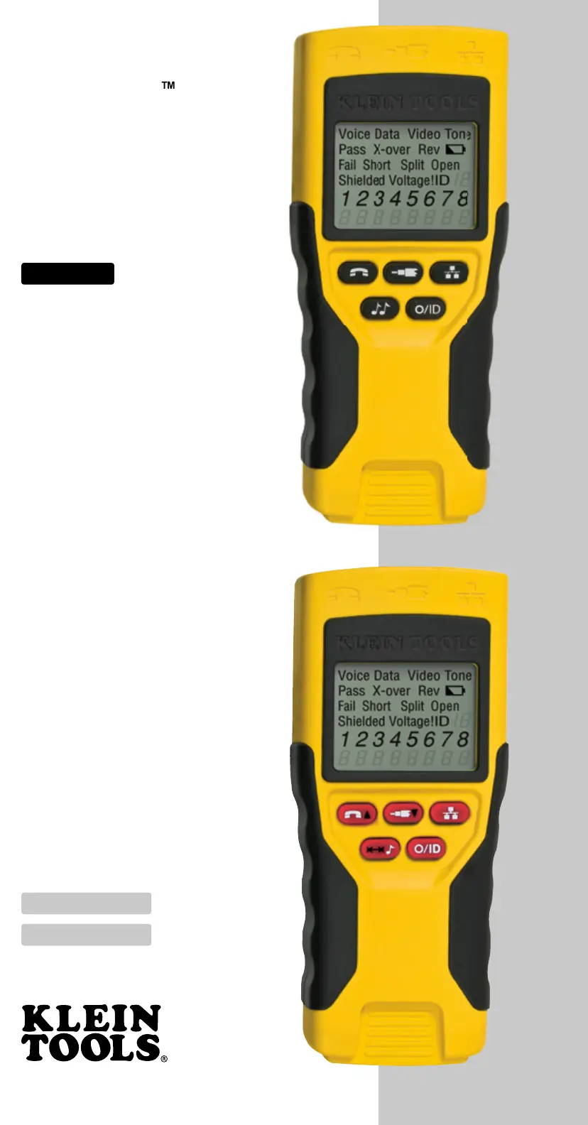
VDV Scout
™
Pro
VDV501-053
VDV Scout
™
Pro LT
VDV501-068
ENGLISH
Español pg. 12
Français pg. 23
•
EXTRA LARGE LCD SCREEN
•
VOICE, DATA, AND VIDEO
CABLE TESTING
•
CABLE ID
•
DETECTS SHORTS, OPENS,
REVERSALS, MISWIRES,
AND SPLIT PAIRS
•
TONE GENERATOR
•
AUTO POWER-OFF
• [LT] LENGTH
MEASUREMENT
VDV501-053
VDV501-068
Product specificaties
| Merk: | Klein Tools |
| Categorie: | Meetapparatuur |
| Model: | VDV Scout Pro VDV501-814 |
Heb je hulp nodig?
Als je hulp nodig hebt met Klein Tools VDV Scout Pro VDV501-814 stel dan hieronder een vraag en andere gebruikers zullen je antwoorden
Handleiding Meetapparatuur Klein Tools

4 Mei 2026
6 Maart 2026
2 Maart 2026
8 Juli 2025
14 April 2025
13 Januari 2025
13 Januari 2025
18 November 2024
12 November 2024
24 September 2024
Handleiding Meetapparatuur
Nieuwste handleidingen voor Meetapparatuur
21 Mei 2026
19 Mei 2026
18 Mei 2026
15 Mei 2026
14 Mei 2026
14 Mei 2026
12 Mei 2026
12 Mei 2026
12 Mei 2026
12 Mei 2026