Klein Tools NCVT-2PKIT Handleiding
Klein Tools Meetapparatuur NCVT-2PKIT
Bekijk gratis de handleiding van Klein Tools NCVT-2PKIT (5 pagina’s), behorend tot de categorie Meetapparatuur. Deze gids werd als nuttig beoordeeld door 67 mensen en kreeg gemiddeld 4.8 sterren uit 5 reviews. Heb je een vraag over Klein Tools NCVT-2PKIT of wil je andere gebruikers van dit product iets vragen? Stel een vraag
Pagina 1/5
SYMBOLS ON TESTER / SÍMBOLOS DEL PROBADOR / SYMBOLES SUR LE TESTEUR
Warning – Risk of electric shock / Advertencia: riesgo de choque eléctrico / Avertissement – Risque d'électrocution
Risk of danger. Important information: It is important that users of this tester read, understand, and follow all warnings, cautions,
safety information, and instructions in this manual before operating or servicing this tester. Failure to follow instructions could result
in death or serious injury.
Riesgo de peligro. Información importante: Es importante que el usuario de este probador lea, comprenda y respete todas las
advertencias, precauciones, instrucciones e información de seguridad incluidas en este manual, antes de poner en funcionamiento el
probador o de realizarle servicios de mantenimiento. No seguir estas instrucciones puede dar lugar a lesiones graves o mortales.
Risque de danger. Information importante: Il est important que les utilisateurs de ce testeur lisent, comprennent et suivent tous les
avertissements, mises en garde, information de sécurité et instructions donnés dans le présent guide avant de faire fonctionner ou de
réparer ce testeur. Le non-respect pourrait entraîner des blessures graves, voire la mort.
Double insulated / Doble aislamiento / Double isolation
Read instructions / Lea las instrucciones / Lire les instructions
Conformité Européenne
Conforms with European Economic Area directives.
Cumple con las normas del Área Económica Europea.
Conforme aux directives de l’Espace économique Européen.
This product has been independently tested by Intertek and meets applicable published standards.
Este producto p1-ha sido probado de manera independiente por Intertek y cumple con las normas publicadas vigentes.
Ce produit a été testé de manière indépendante par Intertek et répond aux exigences des normes applicables.
CAT
IV
For measurements performed at the source of low-voltage installation and outside lines.
Para mediciones realizadas en la fuente de la instalación de bajo voltaje y líneas externas.
Pour des mesures prises à la source d’une installation à faible tension et des lignes extérieures.
3
4
1
5
7
6
8
2
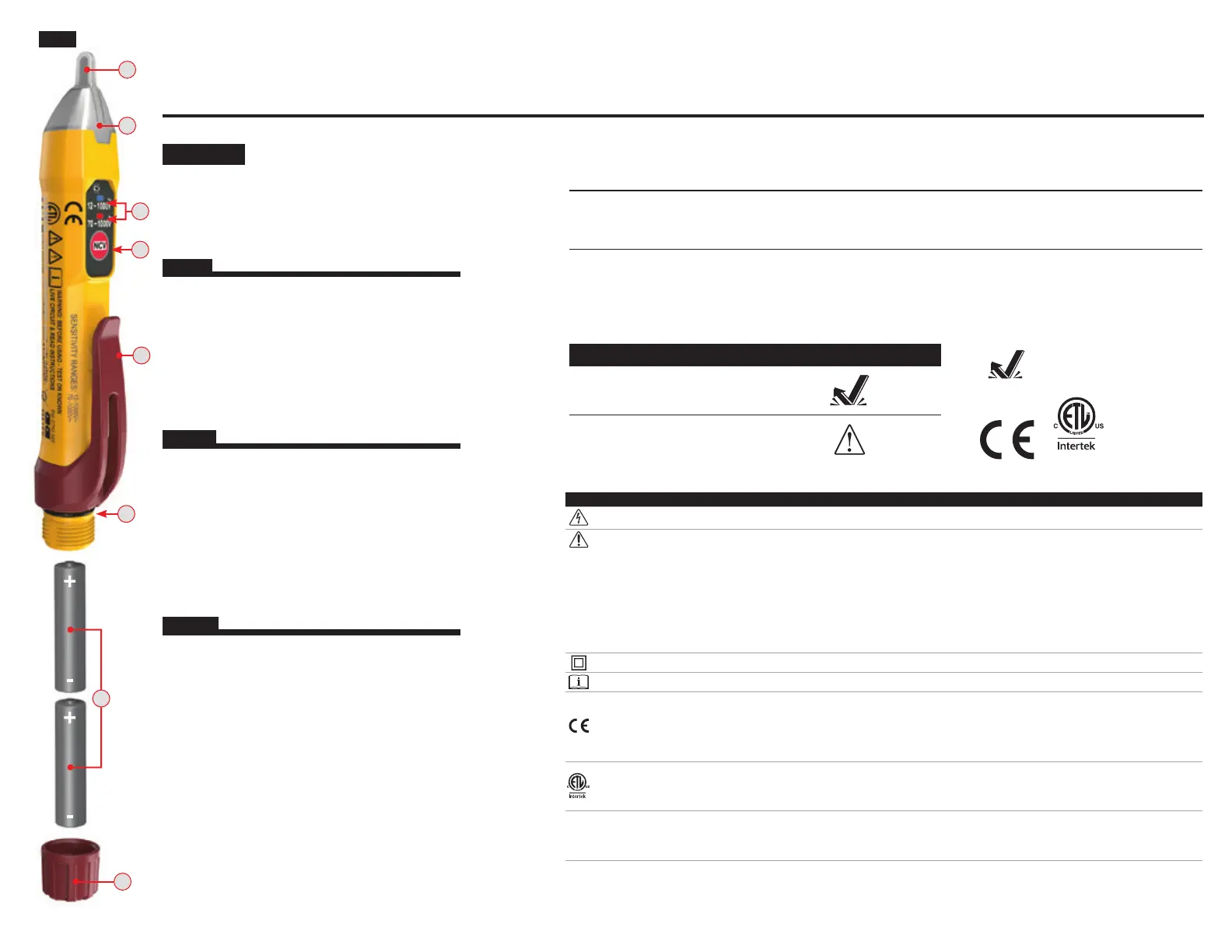
ENGLISH
1.
NCV Power On/Off Button
2.
Power On/Mode LEDs
3.
Voltage Detection LEDs (Inside Tip)
4.
Non-Contact Tip
5.
Pocket Clip
6.
O-ring Seal
7.
Battery Cap
8.
2x AAA Batteries (Included)
NOTE: There are no user-serviceable parts inside tester.
1.
Botón de encendido y apagado "NCV"
2.
LED de encendido/modo
3.
LED de detección de voltaje (en el interior de la punta)
4.
Punta para detección y medición sin contacto
5.
Clip de bolsillo
6.
Junta tórica
7.
Tapa del compartimento de baterías
8.
2baterías AAA (incluidas)
ESPAÑOL
NOTA: El probador no contiene en su interior piezas que
el usuario pueda reparar.
1.
Bouton marche/arrêt NCV (test de tension sans contact)
2.
VoyantsDEL de marche/mode
3.
VoyantsDEL de détection de tension (dans la pointe)
4.
Pointe sans contact
5.
Agrafe pour poche
6.
Joint torique
7.
Couvercle de piles
8.
2pilesAAA (comprises)
FRANÇAIS
REMARQUE: Ce testeur ne contient aucune pièce
réparable par l’utilisateur.
FIG. 1
2 m
CAT IV
1000V
5000573
NCVT-2PKIT
Dual-range Non-Contact Voltage Tester
Probador de voltaje sin contacto de rango dual
INSTRUCTIONS – Electrical Test Kit (English: page 3)
INSTRUCCIONES – Juego de prueba eléctrica (Español: página 4)
INSTRUCTIONS – Trousse de test électrique (Français : page 5)
Testeur de tension sans contact à double plage
DURABILITY / DURABILIDAD / DURABILITÉ
Drop Protection
Protección ante caídas
Protection contre les chutes
6.6 ft.
(2 m)
Safety Rating
Clasificación de seguridad
Cote de sécurité
CAT IV
1000V
• Detects AC voltage from 12 to 1000V with visual & audible indicators
• Two detection ranges: 70 to 1000V and 12 to 1000V
• Auto power-off feature conserves and extends battery life
• Detecta voltaje CA de 12V a 1000V mediante indicadores visuales y audibles
• Dos rangos de detección: 70V a 1000V y 12V a 1000V
• Función de apagado automático que preserva y extiende la vida útil de la batería
• Détecte la présence d’une tension allant de 12 à 1000Vc.a. et la signale au moyen d’indicateurs
visuels et sonores
• Deux plages de détection: 70 à 1000V et 12 à 1000V
• La fonctionnalité d’arrêt automatique permet d’économiser la pile et d’augmenter sa durée de vie
NCVT-2P
Product specificaties
| Merk: | Klein Tools |
| Categorie: | Meetapparatuur |
| Model: | NCVT-2PKIT |
Heb je hulp nodig?
Als je hulp nodig hebt met Klein Tools NCVT-2PKIT stel dan hieronder een vraag en andere gebruikers zullen je antwoorden
Handleiding Meetapparatuur Klein Tools

4 Mei 2026
6 Maart 2026
2 Maart 2026
8 Juli 2025
14 April 2025
13 Januari 2025
13 Januari 2025
18 November 2024
12 November 2024
24 September 2024
Handleiding Meetapparatuur
Nieuwste handleidingen voor Meetapparatuur
21 Mei 2026
19 Mei 2026
18 Mei 2026
15 Mei 2026
14 Mei 2026
14 Mei 2026
12 Mei 2026
12 Mei 2026
12 Mei 2026
12 Mei 2026