Intermatic T1871BR Handleiding
Intermatic Schakelaar T1871BR
Bekijk gratis de handleiding van Intermatic T1871BR (1 pagina’s), behorend tot de categorie Schakelaar. Deze gids werd als nuttig beoordeeld door 19 mensen en kreeg gemiddeld 4.2 sterren uit 5 reviews. Heb je een vraag over Intermatic T1871BR of wil je andere gebruikers van dit product iets vragen? Stel een vraag
Pagina 1/1
MODEL: T1871BR
24 HOUR DIAL TIME SWITCH WITH “SKIPPER
®
’’
TYPE 3R RAINPROOF ENCLOSURE
SUITABLE FOR POOL EQUIPMENT CONTROL IF INSTALLED 5 FT. OR MORE FROM EDGE
OF POOL.TWO NORMALLY OPEN - TWO NORMALLY CLOSED CONTACTS. MAY BE
WIRED AS DOUBLE POLE DOUBLE THROW. 40 A RESISTIVE PER POLE 120-480 VAC;
40 A INDUCTIVE, TUNGSTEN OR 1000 VA PILOT DUTY PER POLE - 120-277 VAC;
2 HP (24 FLA) - 120 VAC; 5 HP (28 FLA) - 240 VAC; 16 A ELECTRONIC BALLAST, 277 VAC
LR3730
UL
HOLOGRAM
LABEL
INDEPENDENTLY WIRED CLOCK MOTOR: 120 VAC, 60 HZ.
CLOCK MOTOR VOLTAGE AND CYCLE MUST BE AS SPECIFIED. TO ORDER
REPLACEMENT, INDICATE PART NO. (WG--) ON MOTOR COVER.
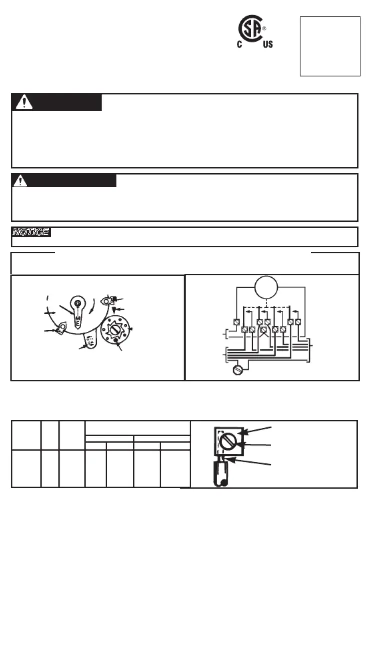
TIME
POINTER
TIME
DIAL
OFF
TRIPPER
MANUAL
LEVER
SKIPPING
SCREW
SKIPPER
WHEEL
DAY
ARROW
ON/
CUTOUT
TRIPPER
120V
60 Hz
SUPPLY
TO
LOAD(S)
CLOCK
MOTOR
GROUND
SCREW
WIRING DIAGRAM
WIRING INSTRUCTIONS: To wire switch follow diagram above. If DOUBLE POLE switch action is required, install jump-
ers (extend supply wires) between terminals 1-6 and 3-8. See gauge selection table for normal service applications.
To make power connections, remove 1/2 inch of insulation from wire ends. Tighten terminal screws firmly (2-18 in-lbs).
Use solid or stranded COPPER only. May use two wires of the same size and type. Motor voltage and cycle conductors
(Hz.) must be as specified.
PRESSURE PLATE
TERMINAL SCREW
MAKE SURE WIRE
INSULATION CLEARS
PRESSURE PLATE
MINIMUM
COPPER
WIRE SIZE
(AWG)
MAX.
LOAD
(AMP)
MIN.
INSUL-
ATION
TEMP(°C)
75°C INSULATION MAX. MOTOR
LOAD (HP)
SINGLE PHASE
3 PHASE
120 V.240 V.208 V.
240 V.
14
12
10
8
15
20
30
40
90
90
90
90
1/2
1
2
-
2
2 1/2
3
5
N/A
N/A
INTERMATIC INCORPORATED
SPRING GROVE, ILLINOIS 60081-9698
154--02076
PROGRAMMING INSTRUCTIONS
1. TO SET “ON” AND “OFF” TIMES: Hold trippers against edge of CLOCK-DIAL, pointing to time (AM or PM) when ON
and OFF operations are desired, tighten tripper screws firmly. For additional tripper pairs on CLOCK-DIAL order
156T1948A.
2. TO SET TIME-OF-DAY: Pull CLOCK-DIAL outward. Turn in either direction and align the exact time-of-day on the
CLOCK-DIAL (the time now, when switch is being put into operation) to the pointer. DO NOT MOVE POINTER.
3. TO SKIP OPERATION(S) ON SELECTED DAY(S): Insert SKIPPING SCREW(S) in SKIPPER WHEEL for day(s) automatic
operation(s) is/are NOT required. Tighten screws firmly. Move MANUAL LEVER to “OFF” and rotate SKIPPER WHEEL to
locate correct day-of-week opposite DAY ARROW--”YESTERDAY” if ON/CUTOUT TRIPPER has not yet advanced wheel
“TODAY” if it has.
OPERATING INSTRUCTIONS
• TO OPERATE SWITCH MANUALLY: Move MANUAL LEVER below CLOCK-DIAL left or right as indicated by arrows. This
will not effect next operation.
CAUTION: TO AVOID SLOW SWITCH ACTION FAILURE, DO NOT OPERATE
SWITCH MANUALLY NOR PLACE A TRIPPER 4 HOURS PRIOR TO
ON/CUTOUT TRIPPER SWITCHING.
• IN CASE OF POWER FAILURE, reset CLOCK-DIAL to proper time-of-day. See programming instructions.
NOTICE
• Rotate timer dial clockwise only.
• Do not move the clock hands on the timer. Moving the clock hands can damage the timer.
WARNING
Risk of Fire or Electric Shock
• Disconnect power at the circuit breaker(s) or disconnect switch(es) before installing or servicing.
• Installation and/or wiring must be in accordance with national and local electrical code requirements.
• Use wires rated at least 90°C - COPPER conductors ONLY.
• For outdoor locations, raintight, or wet location, conduit hubs that comply with requirements of UL514B (standard
for fittings for conduit and outlet boxes) are to be used.
• Replace plastic insulator covering terminals before powering ON.
• KEEP DOOR CLOSED AT ALL TIMES when not servicing.
AVERTISSEMENT
Risque d’incendie ou de choc électrique
• Utiliser des fils classés 90°C minimum - Conducteurs en CUIVRE UNIQUEMENT.
• Pour les emplacements extérieurs, étanches à la pluie ou les emplacements mouillés, des entrées de conduit qui
sont conformes aux exigences de UL514B (norme pour les pièces de fixation pour conduit et boîtes de sortie)
doivent être utilisées
Product specificaties
| Merk: | Intermatic |
| Categorie: | Schakelaar |
| Model: | T1871BR |
Heb je hulp nodig?
Als je hulp nodig hebt met Intermatic T1871BR stel dan hieronder een vraag en andere gebruikers zullen je antwoorden
Handleiding Schakelaar Intermatic

30 Juli 2025
29 Juli 2025
29 Juli 2025
29 Juli 2025
29 Juli 2025
29 Juli 2025
24 Mei 2025
24 Mei 2025
24 Mei 2025
24 Mei 2025
Handleiding Schakelaar
Nieuwste handleidingen voor Schakelaar
20 Mei 2026
20 Mei 2026
19 Mei 2026
18 Mei 2026
12 Mei 2026
12 Mei 2026
11 Mei 2026
11 Mei 2026
8 Mei 2026
6 Mei 2026