Intermatic EH40 Handleiding


Lees hieronder de 📖 handleiding in het Nederlandse voor Intermatic EH40 (8 pagina's) in de categorie Tijdschakelklok. Deze handleiding was nuttig voor 76 personen en werd door 2 gebruikers gemiddeld met 4.5 sterren beoordeeld

Pagina 1/8
Âź
ELECTRONIC 7-DAY WATER -
HEATER TIME SWITCHES
MODELS EH10 AND EH40
WITH BATTERY CARRYOVER
MAN
AUTO
PROG
RUN
TIME
SET
ON
OFF
EVENT DAY HOUR MIN
LOAD
RESET
BATTERY
OWNER/INSTALLER INSTRUCTION MANUAL
ATTENTION: READ CAREFULLY BEFORE ATTEMPTING
TO INSTALL YOUR INTERMATIC TIME SWITCH. FAIL-
URE TO COMPLY WITH INSTRUCTIONS COULD
RESULT IN PERSONAL INJURY AND/OR PROPERTY
DAMAGE! RETAIN FOR FUTURE REFERENCE.
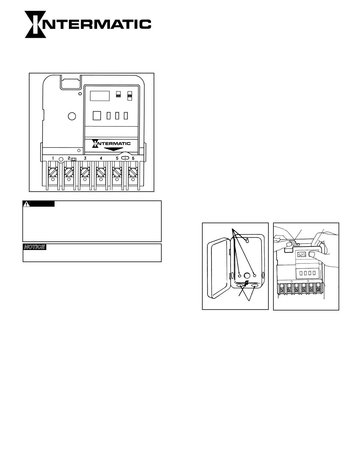
MANUAL (MAN) - AUTOMATIC (AUTO)
(See Fig. 1)
‱MANUAL: Bypasses your program completely; timer
will not resume program until you return switch to
AUTO mode position.
‱AUTOMATIC: For automatically switching at ON/OFF
times; accurate to-the-minute.
PROGRAM (PROG) - RUN - TIME SET
‱PROGRAM: Use this position when programming.
‱RUN: Use this position for normal operation. Be sure to
return to RUN after setting time and program.
‱TIME SET: Use this position to set day and time of day.
ON/OFF - EVENT (the large push button) - Serves a dual
purpose
‱ EVENT: Used for programming (active only when switch
is set at PROG)
‱ ON/OFF: Override (active only when switch is set at
RUN); turns load ON if already off or OFF if already on.
Timer automatically resumes program cycle only when
slide switch is in AUTO. Note that this button is also
accessible without opening the enclosure.
SPECIFICATIONS:
Clock Voltage - Model EH40 - 240V. A.C., 50/60 Hz
EH10 - 120V. A.C., 50/60 Hz
Power Consumption - EH10 - 1.0 W. Max. EH40 - 3.0
W. Max..
Contact Configuration - EH10 (SPST) Single pole-single
throw model-EH40(DPST) Double pole-single throw model
Switch Rating (Per Pole) -
‱ 30 amp inductive/resistive - 120-240V. A.C., 60 Hz
‱ 1 H.P. 120V. A.C., 60 Hz.
‱ 1-1/2 H.P. 240V. A.C., 60 Hz.
‱ 5 amp tungsten, 120-240V. A.C., 60 Hz.
Set Points (Events) - 12 total (6 ON/6 OFF) - Can be
assigned in any combination to weekdays, weekend days,
daily or weekly operation providing up to a maximum of 84
weekly operations (42 ON/42 OFF).
Battery Powered Clock Operation - 3 years minimum,
AA industrial grade alkaline supplied with time switch.
Minimum ON/OFF Time - 1 Minute
Maximum ON/OFF Time - 6 days 23 hours 59 minutes
Shipping Weight - 2.37 Lbs. (1.05 Kg)
Case - Drawn steel, 7-3/4” (19.7 cm) high, 5” (12.7cm)
wide, 3” (7.6 cm) deep; gray finish with lockable spring
hasp, clear see-through viewing window and external over-
ride.
Knockouts - Combination of 1/2 - 3/4” (one on back and
each side, two on bottom)
Wire Size - AWG #10 through #18
GENERAL SAFETY INFORMATION:
WARNING: DISCONNECT THE POWER TO THE TIME
SWITCH AND THE LOADS BEFORE INSTALLING THIS
TIME SWITCH.
1. Mount the time switch in the desired location using the
three mounting holes which are provided. Mount the
time switch at eye level, if possible, providing
sufficient room to the left of the enclosure for the
cover to swing open fully. (See Fig. #2). The time switch
mechanism does not need to be removed from the
enclosure to mount the time switch since the top mount-
ing hole is a slotted type mounting hole. Secure a screw
or other fastener at eye level. The head of the screw
of fastener should be slightly larger than the narrow
portion of the slotted hole to ensure that the time switch
is securely held in place. The remaining two mounting
holes provide a means to secure the time switch.
2. If you do remove the mechanism, refer to Figure #3 and
remove the mechanism from the case by depressing
the catch at the top of the case and pulling out.
CAUTION: DO NOT TOUCH THE CIRCUIT
BOARD COMPONENTS SINCE STATIC DISCHARGE
COULD DAMAGE THE MICROPROCESSOR.
3. Replace the mechanism in the case if it has been
removed, making sure to engage ribs at sides of
mechanism between ears at sides of case before
snapping in place.
4. Lift the left side of the insulator off of the retaining post
and pivot it up and away to expose the terminal
screws.
5. Strip the supply and load wires by removing 1/2 inch of
insulation. DO NOT USE ALUMINUM WIRE. Insert
the wire ends under the proper terminal plates and
tighten the screws firmly. Use any size wire,
AWG #10 through #18. Connect ground wire to
grounding terminal at bottom of case.
6. Replace the plastic insulator.
7. Follow instructions for battery installation. Be sure that
the battery is functioning properly. This can be checked
by seeing that the display is visible. If the display
has scrambled information, check to be sure that
the polarity orientation of the battery is as shown on
the cover label, then press the RESET switch and hold
for at least two seconds. Note that the battery can
easily be replaced without removing the time
switch mechanism or field wiring. Simply press in and
downward (in the direction of the arrow) on the
battery cover which is identified with the word “Battery”.
It is recommended that the battery be replaced with a
“AA” industrial grade alkaline cell at two to three
Fig. 3
Fig.2
Âź
Fig.1
Mounting Holes
Knockouts
Ground
Terminal
Snap Out Catch Tilt Top Forward
Lift Up
To
Remove
http://waterheatertimer.org/How-to-wire-EH40-hot-water-heater-timer.html
________________________________________________________________
year intervals as part of the normal time switch
maintenance observing battery polarity markings when
installing. No other maintenance is required.
8. Place the slide switches in the AUTO and RUN position.
9. Reapply power to the time switch.
10. Press the recessed reset switch for at least two
seconds. The display will show 12:00 A.M. and MO.
Note that the days of the week are identified with the
first two letters of the day (MO for Monday).
The timer is now ready for programming. Refer to the
examples which follow and enter the scheduled events
(set points) required. Assign each of the 12 set
points (EVENTS) entered to whichever day or groups
of days of the week you wish an ON or OFF
operation to occur.
Set Point = Event = ON = OFF
PROGRAMMING STEPS:
SET CURRENT DAY AND TIME
Slide switch to TIME SET. Push DAY until current day
shows, then push HOUR until current hour AM or PM
shows. Now push MINUTE until current minute
shows. Clock is now set. Follow same procedure after
replacing battery or changing time (such as
for daylight saving time).
SET YOUR PROGRAM
Slide switch to PROG. Display will look like this: (-:- -)
‱Press DAYuntil desired program period shows (see
choices in “PROGRAM PERIOD OPTIONS” section
above).
‱Press HOUR until desired “ON 1” hour shows (that
is, the first time each day of the program period that
you want the load to turn ON).
‱Press MINUTE until desired minute shows.
‱Press EVENT to program time for ON 1 (and to
advance to programming for OFF 1).
‱Press DAY again until all seven days of the week
show (or until another desired program period
option shows; see “PROGRAM PERIOD
OPTIONS”).
‱Press HOUR again until desired “OFF 1” hour shows
(that is, the first time each day of the program
period that you want the devices to turn OFF).
‱Press MINUTE until desired minute shows.
‱Press EVENT to set time for OFF 1. You may now
begin setting ON 2, a second ON time, for the same
program period, OR press DAY to change to a
different program period.
‱Repeat above procedure until all desired ON/OFF
programs are set.
PLEASE NOTE: Before you program your timer, or when you
remove the battery, or when you use the RESET, pressing
EVENT will display the bar symbol -:-- ON 1. Repeated press-
ing of EVENT will display all the way through the final bar sym-
bol -:-- OFF 6. Once you program your timer, however, each
actual time setting you make will replace the bar symbol. While
programming, each time you press EVENT you will advance to
the next EVENT.
PROGRAM PERIOD OPTIONS:
Your timer gives you up to 6 different ON and 6 different OFF
settings per program period. You can use all 6 settings per peri-
od, or as few as you like. A program period covers one of these:
‱ALL 7 DAYS OF THE WEEK combined into one -
display shows: MO TU WE TH FR SA SU.
‱MONDAY THRU FRIDAY combined into one -
display shows: MO TU WE TH FR.
‱SATURDAY AND SUNDAY combined into one -
display shows: SA SU
‱EACH INDIVIDUAL DAY OF THE WEEK -
display shows only that day.
‱BLANKDAY EXPLANATION - “BLANKDAY”
follows Sunday after last push of DAY button (when
the lower slide switch is set at PROGRAM). The
purpose of the BLANKDAY is to disable a program
setting on a day.
Program periods with days “combined into one” help you
make settings for those multiple days quickly and conve-
niently while using only one ON/OFF pair. When you set
such a program period, all settings will be identical for
every day of that period.
PERSONAL PROGRAM EXAMPLES
EVENTS
DAY CHECKS ON TIMES OFF TIMES DISPLAYED DAYS & TIMES DISPLAYED
EXAMPLE 1
MO TU WE TH FR SA SU 5:00 PM 10:00 PM ON 1 MO TU WE TH FR SA SU 5:00 PM
OFF 1
EXAMPLE 2
MO TU WE TH FR 6:00 PM 10:00 PM ON 1 MO TU WE TH FR 6:00 PM
OFF 1 MO TU WE TH FR
10:00 PM
SA SU 4:00 PM 8:00 PM ON 2 SA SU 4:00 PM
OFF 2 SA SU 8:00 PM
EXAMPLE 3
MO TU WE TH FR 6:00 AM 9:30 AM ON 1 MO TU WE TH FR 6:00 AM
OFF 1 MO TU WE TH FR 9:30 AM
MO TU WE TH FR 5:30 PM 11:15 PM ON 2 MO TU WE TH FR 5:30 PM
OFF 2 MO TU WE TH FR 11:15 PM
SA SU 3:00 PM 10:00 PM ON 3 SA SU 3:00 PM
OFF 3 SA SU 10:00 PM
EXAMPLE 4
MO TU WE TH 8:00 PM 11:30 PM ON 1 MO TU WE TH 8:00 PM
OFF 1 MO TU WE TH 11:30 PM
FR SA 5:00 PM 2:20 PM ON 2 SU 7:00 PM
(DAY AFTER) OFF 2 SU 10:30 PM
SU 7:00 PM 10:30 PM ON 3 FR 5:00 PM
OFF 3 MO 11:30 PM
ON 4 SA 5:00 PM
OFF 4 TU 11:30 PM
ON 5 “BLANKDAY” -:- -
OFF 5 WE 11:30 PM
ON 6 “BLANKDAY” -:- -
OFF 6 TH 11:30 PM
NOTE: “-:- -” follows Sunday after last push of DAYbutton
(when the slide switch is set at PROG). The purpose of the
-:- - is to cancel a program setting on that day.
REVIEW YOUR PROGRAM
Slide switch to PROG. Press EVENT button to advance
display to each ON or OFF setting. Check days and times
displayed. To make a change, follow instructions under
“SET YOUR PROGRAM”. To delete a displayed set point,
press DAY button until “-:- -” is displayed.
GENERAL FEATURES AND HINTS FOR TROUBLE-
FREE USE
‱BUTTON: When you press a button, there is an advance
of one time unit; holding a button down advances contin-
uously until released.
‱MAINTENANCE: With the exception of battery replace-
ment at 2-3 year intervals, your Intermatic timer is
maintenance-free.
‱AFTER THE INSTALLATION IS COMPLETED, THE
LOCKABLE HASP SHOULD BE MOVED TO THE UP
POSITION TO ENGAGE THE COVER WHEN IT IS
CLOSED. FULL ONE YEAR WARRANTY
If within one (1) year from the date of purchase, this product fails
due to a defect in material or workmanship, Intermatic
Incorporated will repair or replace it free of charge. The warranty
does not apply to (a) damage caused by accident, abuse, mis-
handling or dropping: (b) units which have been subject to unau-
thorized repair, opened, taken apart; (c) units not used in accor-
dance with directions; (d) damages exceeding the cost of the
product. Some states do not allow a limitation of damages, so the
foregoing limitation may not apply to you. This warranty gives you
specific legal rights, and you may also have other rights which
vary from state to state.
This warranty service is available by either (a) returning the prod-
uct to the dealer from whom the unit was purchased, or (b) mail-
ing postage prepaid to the authorized service station listed below.
Please be sure to wrap the product securely when mailing to
avoid damage. This warranty is made by: Intermatic Incorporated,
Intermatic Plaza, Spring Grove, Illinois 60081-9698.
AUTHORIZED SERVICE STATION
INTERMATIC INCORPORATED
4720 West Montrose Avenue
Chicago, Illinois 60641
INTERMATIC INCORPORATED
SPRING GROVE, ILLINOIS 60081-9698
158ET8805 PRINTED IN U.S.A.
TIMER
POWER
LOAD
NEUTRAL
NEUTRAL
1234
Fig. 4 Fig. 5
TIMER
POWER
123456
LINE 1
LINE
LINE
LINE 2
LINE 1 LINE 2
LOAD
120 ≈
240≈
EH10 EH40
- 2 -
See
Pg. 7
See
Pg. 7
Âź
MANUEL-AUTOMATIQUE- (Voir Fig. 1)
‱MANUAL: Mettez le commutateur en cette position pour
contourner entiĂšrement votre programme; la minuterie ne
reprend la programmation que lorsque le commutateur est
remis en position AUTOMATIC (AUTOMATIQUE).
‱AUTOMATIC: Mettez le commutateur en cette position pour
des horaires ON/OFF d’une prĂ©cision Ă  la minute.
PROGRAMMATION-EXÉCUTION-RÉGLAGE
D’HORAIRE
‱PROGRAM (PROGRAMMATION): Mettez le commutateur en
cette position pour la programmation.
‱RUN (EXÉCUTION): Mettez le commutateur en cette position
pour un fonctionnement normale.
‱TIME SET (RÉGLAGE D’HORAIRE): Mettez le commutateur
en cette position pour programmer l’heure.
BOUTON DOUBLE-FONCTION
‱Programmation EVENT (ÉVÉNEMENT) (fonction activĂ©e
seulement lorsque le commutateur est mis en position
PROGRAM)
‱Reprise de contrĂŽle ON/OFF (fonction activĂ©e seulement
lorsque le commutateur est mis en position RUN);
active la marche des dispositifs s’ils sont dĂ©jĂ  en arrĂȘt ou
leur arrĂȘt s’ils sont dĂ©jĂ  en marche.
La minuterie reprend automatiquement le programme Ă  partir
du prochain cycle.
SPÉCIFICATIONS
Tension de l’Horloge
EH10 - 120 VCA, 50/60 Hz
EH40 - 240 VCA, 50/60 Hz
Consommation d’electricite
EH10 - 1.0 Watts max. EH40 - 3.0 Watts max.
Configuration des contacts
Model EH10 Unipolaire/Unidirectionnel
Model EH40 Bipolaire/Unidirectionnel
Valeurs Nominales des Contacts (par pole)
‱30 A. Inductif/Resistif 120/240 VAC, 60 Hz
‱1 CH, 120 VAC, 60 Hz
‱1-1/2 CH, 240 VAC, 60 Hz
‱5 A. Tungstene 120/240 VAC, 60 Hz
Points Reglables (Evenements) Votre minuterie fournit jusqu’a 6
differents relages d’arret par periode de programmation. Vous
pouvez les utiliser tous le 6 en une seule periode ou n’en utiliser
que le nombre qui vous convient.
Dispositif de pile de secours 3 ans minimum.
Duree Marche/Arret min. - 1 min.
Duree Marche/Arret max. - 6 jours, 23 heures, 59 min.
Poids a l’expĂ©dition - 2.37 lbs (1.05 kg)
BoĂźtier - Acier embouti 7-3/4 po (19.7 cm) de haut, 5 po (12.7 cm)
de large, 3 po (7.6 cm) de profondeur; fini gris avec fermeture Ă 
clé.
Debouchures - Combinasion 1/2 - 3/4” (Voir Fig. 2)
Fils - Pour realiser toutes les connexions utiliser des conducteurs
encuivre.
MINUTERIE ÈLECTRONIQUES DE 7
JOURS MODÈLE EH10 ET EH40
avec pile de secours
INSTRUCTIONS D’INSTALLATION ET
MODE D’EMPLOI
ATTENTION: LIRE ATTENTIVEMENT LA PRÉSENTE
NOTICE AVANT D’ÉFFECTUER L’INSTALLATION DE
LA MINUTERIE INTERMATIC. LE NON-RESPECT DES
INSTRUCTIONS RISQUE D’OCCASIONNER DES
BLESSURES ET/OU DES DÉGATS MATÉRIELS!
CONSERVER LA PRÉSENTE NOTICE POUR
RÉFÉRENCE ULTÉRIEURE.
INSTRUCTIONS GÉNÉRALES DE SÉCURITÉ
AVERTISSEMENT: Couper le courant Ă  la source avant
d’installler la minuterie et les dispositifs commandĂ©s ou avant
d’effecteur une intervention quelconque.
1. Se conformer à tous les codes électriques et de sécurité
locaux.
2 Si l’interrupteur de coupure du courant n’est pas visible
pendant le travail, le verrouiller en posiiton d’arrĂȘtĂ© et y
apposer une étiquette en vue de prévenir toute mise en
marche accidentelle.
3. Le boĂźtier de cette minuterie doit ĂȘtre mis Ă  la terre.
4. Ne pas dépasser la capacité maximale de courant de cette
minuterie.
5. Toujours remettre en place l’isolateur de borne en plastique
avant de mettre la minuterie sous tension.
INSTALLATION
1. Monter la minuterie à l’endroit voulu au moyen des trois trous
de montage prévus à cette effet. Monter la minuterie à hauteur
des yeux, si possible, ef en laissant suffisamment de place Ă 
la gauche du boütier pour permettre au couvercle de s’ouvrir
complĂštement. (Voir Fig. 2) Il n’est pas nĂ©cessaire de
retirer le mécanisme de la minuterie de son boßtier pour
effectuer le montage étant donné que le trou de
montage supérieur est du type à fente. Placer une vis ou un
autre dispositif de fixation dans la parol Ă  hauteur des yeux.
La tĂȘte de la vis ou du dispositif doit ĂȘtre lĂšgĂ©rement plus
grosse que la partie étroite du trou de montage de façon à ce
que la minuterie soit fermement fixée à son emplacement.
Les deux autres trous de montage sont accessibles sans qu’il
soit nécessaire de démonter le mécanisme de la minuterie.
Ils assureront un montage permanent et stable de la minuterie.
2. Si l’on retire le mĂ©canisme de la minuterie de son boĂźtier,
procĂ©der comme indiquĂ© Ă  la Figure 3 en pesant sur l’ergot
qui dépasse du haut du boßtier et en tirant sur ce dernier.
ATTENTION: NE PAS TOUCHER LES COMPOSANTS DE
LA PLAQUETTE DE CIRCUIT. UNE DÉCHARGE
D’ÉLECTRICITÉ STATIQUE RISQUE D’ENDOMMAGER
LE MICROPORCESSEUR.
3. Replacer le mécanisme dans le boßtier le cas échéant.
4. Soulever le cĂŽtĂ© gauche de l’isolateur du point d’attache et le
faire pivoter vers le haut et vers l’extĂ©rieur pour exposer la
barrette Ă  bornes.
5. DĂ©nuder les fils d’alimentation et de charge en enlevant 1/2 po
(1.2 cm) d’isolant. NE PAS UTILISER DE FILS
D’ALUMINUM. (Voir Fig. 4 ou 5.) InsĂ©rer les extrĂ©mitĂ©s des fils
dans les plaques de borne appropriées et resserrer lels vis
fermement. Utiliser des fils AWG #10 Ă  18. Relier le fil de terre
à la borne prévue à cet effet en bas du boßtier.
6. Replacer l’isolatteur en plastique.
7. S’assurer que la pile fonctionne bien. Ceci peut se faire en
s’assurant que, l’affichage est bien allumĂ©. Si l’affichage
donne des informations brouillĂ©es, peser sur l’interrupteur
de RAZ (RESET) et le maintenir enfoncé pendant trois à
cinq secondes. On notera que la pile est montée en usine
et qu’elle se remplace facilement sans avoir, Ă  dĂ©monter
le mécanisme de la minuterie ni le cùblage. Il suffit de peser
vers l’intĂ©rieur et vers le bas (dans la direction de la flĂšche) sur
le couvercle de la pile (oĂč est inscrit le mot “Battery”). Il
est recommandé de remplacer la pile par une pile industrielle
de type AA standard tous les deux ou trois ans en prenant
soin de respectter les indications de polaritté de la pile. Ceci
fait partie de l’entretien normal de la minuterie et aucun
autre entretien n’est requis.
8. Placer les sélecteurs en position AUTO (automatique) et
RUN.
9. Remettre la minuterie sous tension.
10.Peser sur l’interrupteur de RAZ (RESET) pendant trois à cinq
secondes. L’affichage indique alors 12:00 A..M. 1. La minuterie
est prĂȘte Ă  ĂȘtre programmĂ©e. Se reporter au tableau ci-bas et
entrir les événements aux heures voulues. Assigner chacun
des entrĂ©es Ă  n’importe quel(s) jour(s) de la semaine oĂč l’on
desire que la minuterie mette un dispositif commandé
sous tension ou hors tension. On notera que la programmation
de deux arrĂȘts consĂ©cutifs permet Ă  l’utilisateur de mettre un
dispositif sous tension manuellement, aprĂšs les heures
normales de travail par exemple, et de laisser la minuterie le
mettre hors tension automatiquement. Ceci permet
d’économiser de l’énergie aprĂšs les heures normales
d’occupation des locaux tout en permettant une extinction
ou un arrĂȘt automatique du dispositif. On notera de mĂȘme
qu’il est possible de programmer plusieurs arrĂȘts consĂ©cutifs,
ce qui offre alors plusieurs heures d’extinction ou d’arrĂȘt
autotmatique des dispositifs.
- 3 -


Product specificaties

Merk: Intermatic
Categorie: Tijdschakelklok
Model: EH40

Heb je hulp nodig?

Als je hulp nodig hebt met Intermatic EH40 stel dan hieronder een vraag en andere gebruikers zullen je antwoorden


Handleiding Tijdschakelklok Intermatic

Intermatic

Intermatic EH40 Handleiding

24 September 2022

Handleiding Tijdschakelklok

Nieuwste handleidingen voor Tijdschakelklok