InSinkErator Evolution 100 Handleiding


Lees hieronder de 📖 handleiding in het Nederlandse voor InSinkErator Evolution 100 (2 pagina's) in de categorie Niet gecategoriseerd. Deze handleiding was nuttig voor 22 personen en werd door 2 gebruikers gemiddeld met 4.5 sterren beoordeeld

Pagina 1/2
English only (Australia, New Zealand, UK, Hong Kong, and Ireland)
www.insinkerator.com
©2009 InSinkErator, a division of Emerson
Electric Co. All Rights Reserved.
1b
1a
2
3
4
5
6
7
8
12
11
10
13
14
15
19
20
21
22
16
17
18
23
24
25
22
26
27
28
29
30
9
Food waste disposers provide an environmentally responsible alternative to transporting food waste to landfills. And they ca n help reduce
greenhouse gas emissions. At capable wastewater treatment plants, food waste can be converted to biosolids and used as fertilizer. Capable
plants can also capture methane gas and recycle it as an energy source. (Check the plant in your area.)
Read throu gh the entire Installation, Care & Use manual before installing the disposer. Determine which of the tools, materials, and
accessories you will need before you begin. Make sure you have all necessary disposer parts before installing the disposer.
NOTE: The Evolution models grind much finer than any other disposer. For this reason you may notice that it takes a little longer to grind
some food waste. Due to the Evolu tion 200 model’s microprocessor, users will experience a fractional second delay when starting on all
Evolution 200 models. This is completely normal.
NOTE: must In Australia, all plumbing and electrical work be completed by a qualified tradesperson. This product may require approval of the
relevant regulator and/or the sewerage system operator. Disposer must be installed to AS/NZS 3500.2 standard requirements.
NOTE: Make sure that the installation of this appliance is allowed by the authorities.
TOOLS & MATERIALS YOU WILL NEED:
Slotted Screwdriver, Adjustable Pliers, Safety Glasses
TOOLS, MATERIALS, AND ACCESSORIES YOU MAY NEED:
Phillips Screwdriver, Drain Auger, 9.5 mm Electrical Clamp, Wire Nuts (2), 38 mm Drain Trap, 33 mm Hole Drill, Hammer, Hacksaw, Water Hose
Clamp, Pipe Wrench, Copper Earth Wire, Dishwasher Drain Connection Kit, Electrical On/Off Switch, Drain Tube Extension
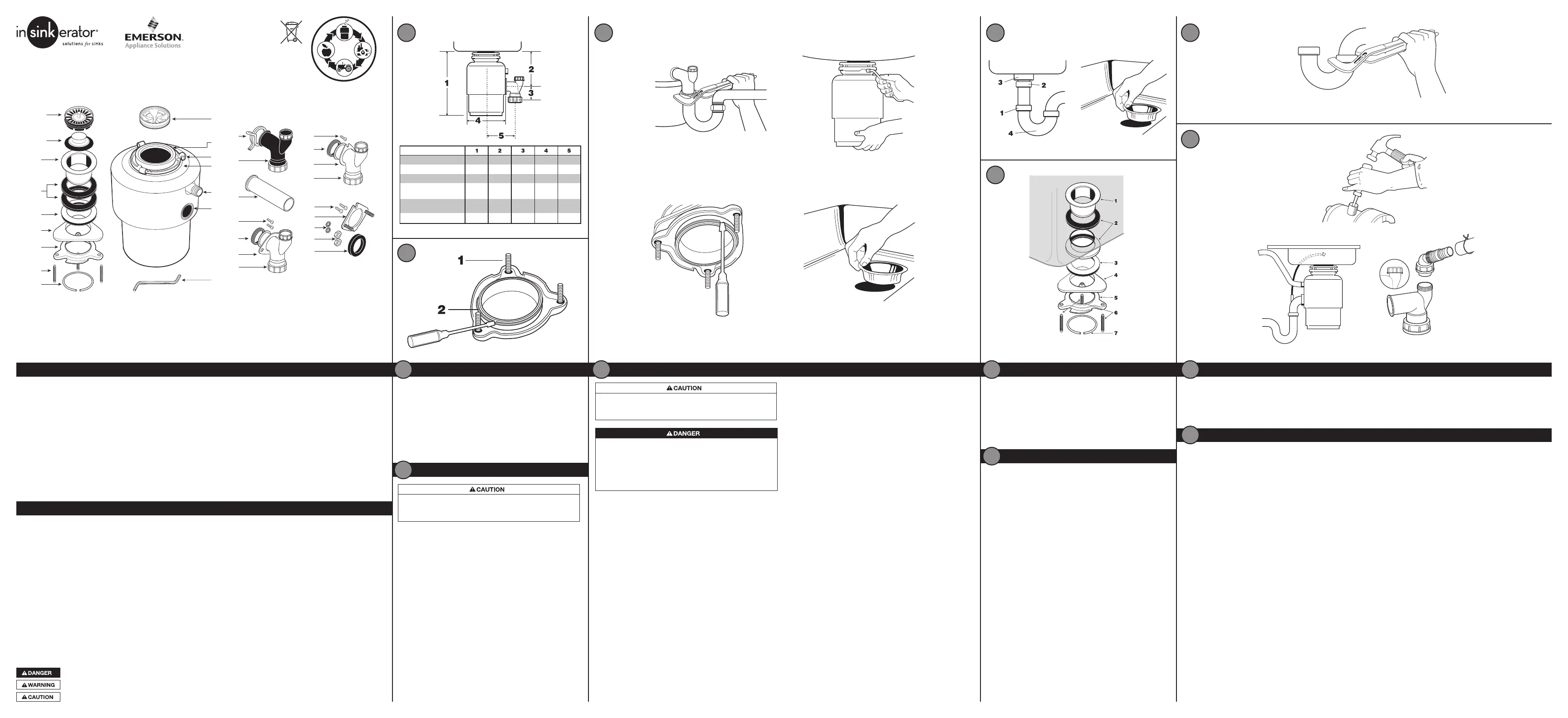
MOUNTING ASSEMBLY
1a. Stra iner Basket and Plug
(Evolution models)
1b. Stopper (Models 65, 55, 45, LC-50)
2. Sink Flange
3. Rubber Gaskets (2)
4. Fiber Gasket (optiona l)
5. Backup Ring
6. Mounting Ring
7. Screws (3)
8. Snap Ring
DISPOSER
9. Sound Bafe (Evolution models,
Model 65)
10. Mounting Gasket/Splash Baffle
11. Lugs
12. Lower Mounting Ring
13. Dishwasher Inlet
14. Discharge Outlet
15. Wrenchette
DISCHARGE ASSEMBLY #4
(Australia Model LC-50 connected to
Caroma Connector not supplied)
26. Bolt (1) 19 mm 1/4-20 UNC
27. Metal Flange (Use to connect
to proper Caroma Connector)
28. Metal Washers (2)
29. Nuts (2)
30. Rubber Gasket
DISCHARGE ASSEMBLY #5
(Australia Models 65, 55, 45; connected to
Caroma Connector not supplied)
26. Bolts (2) 19 mm 1/4-20 UNC
28. Metal Washers (2)
30. Rubber Gasket
DISCHARGE ASSEMBLY #1
(Evolution models)
16. Hose Clamp
17. Black Elbow Discharge Tube
(38 mm diameter/Evolution flange)
18. Straight Discharge Tube 40.3 mm OD
(Australia installation only)
DISCHARGE ASSEMBLY #2
(Models 65, 55, 45)
19. Bolts (2) 13 mm 1/4-20 UNC
20. Rubber Gasket
21. Metal Flange
22. White Elbow Discharge Tube
(38 mm diameter/non-Evolution flange)
DISCHARGE ASSEMBLY #3
(LC-50 for household installation)
23. Bolt (1) 19 mm 1/4-20 UNC
24. Rubber Gasket
25. Metal Flange
22. White Elbow Discharge Tube
(38 mm diameter/non-Evolution flange)
230-240V, 50Hz
for Australia and New Zealand
220-240V, 50Hz
for UK/Hong Kong/Ireland
Part No. 75978 REV. A
FOOD WASTE DISPOSER INSTALLATION, CARE & USE MANUAL
PARTS LIST (May vary depending on model)
Danger indicates an imminently hazardous situation which, if not avoided, will result in death or serious injury.
Warning indicates a potentially hazardous situ ation which, if not avoided, could result in death or serious injury.
Cau tion indicated a potentially hazardous situation, which, if not avoided, may result in minor or moderate injury.
31.8 cm 16.8 cm 6.4 cm 18.5 cm 13.1 cm
31.8 cm 16.8 cm 6.4 cm 17.3 cm 13.1 cm
31.8 cm 16.8 cm 6.4 cm 15.9 cm 13.1 cm
36.9 cm 19.3 cm 6.4 cm 20.6 cm 14.9 cm
34.4 cm 18.5 cm 6.4 cm 23.4 cm 16.8 cm
31.2 cm 17.1 cm 6.4 cm 20.5 cm 16.8 cm
(Evolution) 200-1, -3
(Evolution) 100-1, -3
Model 65-1B, -3B
Model 55-1B,
-1B A/S, -3B, -3B A/S
Model 45-1B,
-1B A/S, -3B
LC50-12, -13
CHECK INSTALLATION DIMENSIONS
1. Disposer Height
2. Distance from bottom of sink bowl to centerline of discharge outlet.
(Add 12 mm when stainless steel sink is used.)
3. Distance from centerline of the discharge outlet to end of
discharge tube.
4. Disposer Width
5. Distance from disposer vertical centerline to centerline of
trap connection.
To properly drain and prevent standing water in the disposer, the waste
pipe entering the wall must be lower than the disposer discharge outlet.
DISCONNECT SINK DRAIN
1. Loosen nut (1) at top of trap (4) with pipe wrench (see Figure 4.1).
2. Loosen nut (2) at top of extension pipe. Remove extension pipe.
3. Loosen nut (3) at base of sink flange.
4. Push sink flange up through sink hole and remove it (see Figure 4. 2).
5. Clean sink flange area of any putty or other debris.
The sink hole may have to be enlarged to accept the disposer NOTE:
sink flange. Sink hole enla rgement tools are available from your
InSinkErator Dealer.
1
2
1
2
2.1
3
4.33.3
2.31.3
2.41.4
5.1
1. Turn mounting assembly over (see Figu re 2.1) and loosen three
mounting screws (1) until you can access snap ring (2).
2. Use screwdriver to pry snap ring off of sink flange. Mounting
assembly will now come apart.
3. Set mounting assembly aside. This will be used in Instruction 5.
IF REPLACING AN EXISTING DISPOSER,
CONTINUE WITH INSTRUCTION 3.
IF THIS IS A FIRST TIME INSTALLATION,
SKIP AHEAD TO INSTRUCTION 4.
DISASSEMBLE NEW DISPOSER
MOUNTING ASSEMBLY Reference Figure 5.1.
1. Place one of two rubber gaskets (2) under sink flange (1). Ensure sink
hole area is clear of debris and place sink flange/gasket into sink hole.
You may wish to place a weighted object in the sink to hold the sink
ange in place. (Place a towel under object to prevent scratching.)
2. Working from under the sink, slip second rubber gasket (2),ber
gasket (optional) (3) a nd metal backup ring (4) (flat side up) over the
sink flange.
3. Holding second rubber gasket,ber gasket (optiona l) and metal
backup ring in place, slip mounting ring (5) over sink flange so it seats
against backup ring.
4. With the rubber gasket,ber gasket (optional), backup ring, and
mounting ring tight against sink bottom, slide snap ring (7) onto sink
ange until it pops into groove on flange.
5. Tighten three mounting screws (6) up to sink until mounting assembly
is seated tightly and evenly against sink.
ATTACH UPPER MOUNTING ASSEMBLY TO SINK
4
5
4
5
REMOVE EXISTING DISPOSER
3
PERSONAL INJURY
To avoid personal injury, do not position your head or body under
disposer; the unit could fall during installation.
ELECTRICAL SHOCK
To avoid electrical shock, disconnect power before installing or
servicing disposer. Turn off electrical power at fuse box or circuit
breaker or if equipped unplug disposer electrical power plu g from
wall outlet.
Improper connection of equ ipment earth (grounded) conductor
can result in electric shock.
1. If your disposer is equipped with an electric plug and cord
connection, unplug power plug from electrical wall outlet.
If your disposer is not equipped with an electrical plug and
cord connection, contact an electrician to disconnect the old
disposer plus install an earth (grounded) electrical wall outlet for
the new disposer connection that must be compliant to all local
electrical codes.
2. Disconnect drain trap from disposer waste discharge tube with
adjustable pliers (see Figure 3.1). Also disconnect dishwasher drain
connection, if applica ble.
3. Support disposer with one hand and insert end of wrenchette or
screwdriver into right side of one mounting lug on lower mounting
ring (see Figure 3.2). Lift disposer slightly and remove from mounting
by pushing or pulling wrenchette or screwdriver to left (disposer may
be heavy; provide support).
4. Loosen three mounting screws, pry snap ring off with screwdriver,
and remove old mounting assembly (see Figure 3.3). Some mounting
assembly removal requires additional tools.
5. Push old sink fla nge up through sink hole (see Figure 3.4). Skip ahead
to Instruction 5.
7.1
7.37.2
Failure to clean sink waste pipe line may result in waste pipe blockage.
1. Remove trap. (See Figure 6.1)
2. With drain auger, clear away all hardened waste material in horizontal drain line running from drain trap to main pipe.
IF YOU ARE NOT CONNECTING A DISHWASHER TO DISPOSER, SKIP AHEAD TO INSTRUCTION 8.
DOES NOT APPLY TO AUSTRALIA/NEW ZEALAND In Australia, it is
suggested that the dishwasher units be connected to IPLEX/ COROMA
dishwasher spigot for maximum efficiency.
Wastewater from a dishwasher can be plumbed into the disposer
through the inlet access on the upper part of the disposer. There is a
plug on the inside of the inlet tube on all models. Once removed, the
knockout plug cannot be replaced.
NOTE: If the dishwasher connection is made without removing the plug,
the dishwasher may overow. (Connections must comply with local
plumbing codes.)
REMOVE KNOCKOUT PLUG
1. Lay disposer on its side and insert screwdriver into dishwasher inlet so
tip rests on outer edge of knockout plug.
2. Tap end of screwdriver handle with hammer until molded plug brea ks
loose (see Figure 7.1).
3. Remove loose knockout plug from inside disposer.
DISHWASHER ATTACHMENT AND OVERFLOW CONNECTION
CLEAN SINK WASTE PIPE
6
7
THE SINK OVERFLOW
The sink overflow may be connected to the overflow tube on the
tailpipe (see Figure 7.2). Remove the overflow connector cap and
blue plastic seal from the end of the overow tu be (see Figure 7.3).
Utilizing the nut, connect the overow hose to the tailpipe.
NOTE: The straight discharge tu be for use in Australia does not
have an overow connection tube. In the UK, waste trap kit, which
does not include the sink overflow kit, is available from your local
InSinkErator dealer.
6
7
6.1
(installation continued on reverse)
InSinkErator Division
Suite 6, Building 6
Hatters Lane,
Croxley Green Business Park
Watford HERTS WD18 8YH
United Kingdom
Sales Tel: (0) 1 923 297 880
Service Tel: (0) 800 389 3715
www.insinkerator.co.uk
Parex Industries Ltd.
5 Tolich Place, Henderson
P.O. Box 21-102
Auckland, New Zealand 0610
Sales Tel: 64 9 836 6566
Service Tel: 0800 200 510
www.parex.co.nz
InSinkErator Division
471 Mountain Highway
Bayswater Vic 3153, Australia
Sales Tel: 61 03 9720 5599
Service Tel: 1 300 136 205
www.insinkerator.com.au
InSinkErator Division
Emerson Electric Co.
4700 21st Street
Racine, WI 53406-5093
USA
Sales/Service Tel:
262-554-3652
www.insinkerator.com/
worldmap.html
KAL Group
4078 Kingswood Road,
Citywest Business Park
Dublin, Ireland
Tel: 01 413 6481,
01 413 6400
Fax: 01 413 6464
Email: info@kal.ie
PERSONAL INJURY
Wearing safety glasses is recommended during the installation of
the food waste disposer.
Evolution 100: Australia Pat. No. 307603, 307769, 308385, and other foreign patents pending
Evolution 200: Australia Pat. No. 307601, 307769, 308695, 308385, and other foreign patents pending
Air Switch (Evolution 200, Evolution 100, Model 65,
Model 55-1B A/S, 55-3B A/S and 45-1B A/S):
The Evolu tion 200, Evolution 100, and Model 65 disposers include a
built-in air switch (Satin Nickel and Chrome finishes). An air switch
activates/turns off the unit by sending a pulse of air to the control box.
AIR SWITCH INSTALLATION
The air switch includes two different button finishes. If you wish to
change the button finish (optional), simply pry off the existing button
and snap the other button finish onto the bellows. (See Figure 11.2)
1. Drill a 33 mm wide hole into the kitchen work top, or the corner of
the sink u nit, at the most convenient point for use. Some sink units
may already have a suitable hole in them which can be exposed by
removing the cap.
2. Remove the nut from the push button bellows, while keeping the
stainless steel washer and rubber ga sket in place. Push one end of
the PVC tubing onto the spout of the push button bellows, feed the
other end of the tube through the hole in the work top and through
the nut underneath the work top. (See Figure 11.3)
3. Fit the push button bellows in the hole and then screw up the nut
underneath the work top until it is hand tight. Do not use a wrench
to tig hten the nut. (See Figure 11.4)
4. Ta ke the other end of the air tube and firmly push it over the spout
of the air switch, which is located on the underside of the waste
disposer. (See Figu re 11.5)
DISABLING THE AIR SWITCH
The air switch can be disabled if wall switch operation is preferred.
The disposer is shipped with the switch in the “off ” position.
1. Push one end of the PVC tu bing provided onto the spout of the push
button bellows. (See Figure 11.3)
2. Ta ke the other end of the air tube and push it over the spout of the
air switch, which is located on the u nderside of the waste disposer.
(See Figure 11.5)
3. Depress the air switch one time until you hear the switch “click.
Remove and discard the push button bellows and PVC tubing. The
disposer may now be activated by a wall switch.
The disposer installation is complete. Read all operating and
safety instructions in Instruction 12 before operating the disposer.
Lastly, place stopper in sink in close position. Fill sink with water,
remove stopper, turn disposer on and check for leaks.
CONNECT DISPOSER TO ELECTRICAL SUPPLY
ELECTRICAL SHOCK
To avoid electrical shock, disconnect power before installing or
servicing disposer.
If you are not thoroughly familiar with electric power, contact a
qualified electrician to connect disposer to electrical circuit.
If three-prong, earth (grounded) plug is used, plu g must be
inserted into three-hole, earth (grounded) receptacle.
Do not modify plug provided with unit (if applicable).
Improper connection of equipment earth (grou nded) conductor
can result in electric shock.
All wiring must comply with local electrical codes.
Do not attach earth wire (ground wire) to ga s supply pipe.
Do not reconnect electrical current at main service panel until
proper earth (grounded) ou tlets are installed.
If the supply cord is damaged, it must be replaced by the
manufacturer, its service a gent or similarly qualified-persons
in order to avoid a hazard.
11
11
8.3
8.2
8.1
8.4
MOD EL X X – XX
S/N X XXXX XXXX X
PUS H RED BUTTO N
TO RE SE T
Clear any objects from inside the disposer grind chamber before
mounting the disposer to the sink.
1. This product must be installed so that the motor reset button
located on the bottom of the disposer is readily accessible.
Keep this space clear of all objects.
2. Prior to connecting disposer to mou nting assembly, detach the
perforated portion of the specification la bel found at the base
of the disposer, and set aside for Instruction 9 (See Figure 8.1).
3. Position disposer with three mounting tabs (1) aligned in
position to slide over mounting tracks (2). (See Figure 8. 2)
4. Lift disposer, insert top end (mounting gasket) into mounting
assembly, and turn lower mounting ring to right (with
wrenchette or adjustable pliers) until mounting tabs lock over
ridges (3) on mounting ring tracks (see Figure 8.3). Make sure
all three mounting tabs are locked over ridges. Disposer will
now hang by itself.
EVOLUTION 200 AND EVOLUTION 100, MODEL 65
Insert sound baffle into sink opening, with flat side upward. (See
Figure 8.4)
CONNECT DISPOSER TO MOUNTING ASSEMBLY
PERSONAL INJURY
To avoid personal injury, do not position your head or body
under disposer; the unit could fall during installation.
8
8
MODEL XX – XX
S/N XXXXXXXXXX
PUSH RED BUTTON
TO RESET
10.3 10.4
10.5 10.6
10.210.1
(FLANGED DISCHARGE
PIPE NOT PROVIDED)
(FLANGED DISCHARGE
PIPE NOT PROVIDED)
AUSTRALIA ONLY
AUSTRALIA ONLY
DISCHARGE TUBE INSTALLATION (EVOLUTION 200 AND
EVOLUTION 100 )
1. Place discha rge tube (2) into Anti-Vibration Tailpipe Mount
. Secure
with spring type hose clamp (1). (See Figu re 10.1)
UK, NEW ZEALAND, HONG KONG AND IRELAND DISCHARGE
TUB E INSTALLATION (MODELS 65, 55, 45)
1. Place metalange (6) over discharge tube (8). Insert rubber
gasket (5) with gasket lip facing the metal fla nge into discharge
tube. (See Figu re 10.3)
2. Secure metal flange and discharge tube to disposer with two
13 mm bolts (7).
ATTACH DISCHARGE TUBE TO WASTE DRAIN PIPE
This specication label contains important information you will
need to know in the event service is required.
1. Apply the label to the front side of the disposer, where it can
be easily read.
ATTACH SPECIFICATION LABEL
10
9
10
OPERATING INSTRUCTIONS (EVOLUTION 200 AND EVOLUTION 100)
1. Remove strainer basket and plug from sink opening and run cold water.
2. Tu rn on wall switch or press air switch (see Figu re 12.1) to
start disposer.
3. Slowly insert food waste into disposer and position strainer basket
and plug in upright position (allowing water to run through) to
minimize noise and possible ejection of material while grinding
(See Figure 12.2).
4. After grinding is complete, tu rn disposer off and ru n water for a t
least 15 seconds to flu sh drain line.
5. Strainer basket and plug also acts as a stopper in the lower position.
(See Figure 12.3)
OPERATING INSTRUCTIONS (MODELS 65, 55, 45, LC-50)
1. Remove stopper from sink opening and run cold water.
2. Tu rn on wall switch or press air switch (see Figu re 12.1) to
start disposer.
3. Slowly insert food waste into disposer and position stopper to
minimize noise and possible ejection of material while grinding.
(See Figure 12.4)
4. After grinding is complete, tu rn disposer off and ru n water for a t
least 15 seconds to flu sh drain line.
DO...
Grind food waste with minimum cold waterow of 5.7 liters per
minute (1-1/2 G.P.M.).
Grind hard material such as small bones and fru it pits to clean
inside of grind chamber.
Grind citrus, melon rinds, vegetables, and coffee grounds.
After grinding, ru n water for at least 15 seconds to flush drain line.
Switch off or unplug the appliance before attempting to free a
jammed rotor with an implement.
Maintain the area undernea th the disposer of any objects to be sure
you have access to the disposer reset button.
DON’T...
Don’t use hot water when grinding food waste (althou gh hot water
ca n be drained into disposer between grinding periods).
Don’t turn off water or disposer u ntil grinding is completed and only
sound of motor a nd water running is heard.
Don’t grind large amounts of egg shells orbrous materials like corn
hu sks, artichokes, etc., to avoid possible pipe blockage.
Don’t grind non-food waste of any kind.
Don’t use this appliance to dispose of hard materials such as glass
and metal.
Don’t ever pour fats, oils or grease down the sink – it will block your
drains and the sewerage system.
INSTRUCTIONS PERTAINING TO RISK OF FIRE, ELECTRICAL SHOCK, OR INJURY TO PERSONS (SAVE THESE INSTRUCTIONS)
InSinkEra tor products are guaranteed against defects in material and
workmanship for the period of the guarantee from the date of purchase.
Evolution 200: 6 years Evolution 100: 5 years
Model 65: 4 years Model 55: 3 years
Model 45: 2 years LC-50: 1 year
SERVICE
If service is required, contact an InSinkEra tor Authorized Service
Center (see enclosed list) or your dealer. Guarantees are void if you
remove your disposer after installation and attempt to repair it, or if
the disposer is used for commercial purposes.
IN-HOME FULL SERVICE GUARANTEE
12.4 12.612.5
12.312.2
12.1
MO DEL XX – XX
S/N XXXXXXXXXX
PU SH RED BU TTONTO RESET
MODE L XX – X X
S/ N XX XXX XX XX X
PU SH RED B U T T ON
T O RE SET
Whe n using electronic appliances, basic precautions are always
to be followed, including:
In Australia, product may require approval of the relevant regulator
and/or the sewerage system operator.
If the air switch or wall switch fails to shut off or turn on disposer,
unplug power cord plug and contact your qualied trade person.
This product is designed to dispose of normal hou sehold food
waste; inserting materia ls other than food waste into disposer
could cause personal injury and/or property damage. To reduce
the risk of injury, do not u se the sink containing the disposer for
purposes other than food preparation (such as baby bathing or
washing hair).
This appliance is not intended for use by persons (including
children) with reduced physical, sensory or mental ca pabilities,
or lack of experience and knowledge, unless they have been given
supervision or instruction concerning use of applia nce by a person
responsible for their safety. Children should be supervised to
ensure that they do not play with disposer. To reduce the risk of
injury, close supervision is required when an appliance is used
near children.
When attempting to loosen a jam in the food waste disposer,
switch off or u nplug the appliance before attempting to free a
jammed rotor. Use a self service wrenchette as described in
the Releasing Disposer Jam section.
Use long-handled tongs or pliers to remove objects from disposer.
To reduce the risk of injury by materials that are expellable by a waste
disposer, do not operate Evolution disposers without the sound
baffle in place (See Figure 8.4). Place stopper in sink opening as shown
in Figure 12.2 or 12.4. Do not put the following into a disposer: clam
or oyster shells, caustic drain cleaners or similar products, glass,
china , or plastic, large (whole) bones, metal (such as bottle caps,
steel shot, tin cans, or utensils), hot grease or other hot liquids.
Replace sound bafe/mounting gasket/splash baffle when worn to
help prevent entry or ejection of materia l and water.
When not u sing disposer, leave stopper in place to reduce risk of
objects falling into disposer. Make sure disposer power switch is
turned off.
Before pressing reset button, attempting to clear jam, or removing
objects from inside disposer, make sure disposer power switch is
turned off.
Do not insert hands or fingers into disposer.
FIRE HAZARD: Do not store flammable items such as rags, paper,
or aerosol cans near disposer. Do not store or use gasoline or other
flammable vapors and liquids in vicinity of disposer.
Do not dispose of the following in the disposer: paints, solvents,
household cleaners and chemicals, automotive fluids, plastic wrap.
Dont fill disposer with a lot of vegetable peels all at once. Instead, turn
the water and disposer on first and then feed the peels in gradually.
Don’t waste food. Nearly a quarter of the food we buy is thrown
away untou ched: salad, bread and ca kes and fruit head the list.
Three tips to stop waste and save you money: only buy, or cook,
the portions you need for the meal; check the fridge and cu pboard
for food you haven’t eatenmake it your next snack or freeze it;
and make sure you lea ve that food off your next shopping list!
CLEANING DISPOSER
Over time, grease/food particles may accu mulate in the grind
chamber and bafe, causing a n unpleasant odor. To clean
the disposer:
1. Turn of f disposer and disconnect power supply.
2. Reach throu gh sink opening and clea n underside of splash
bafe and inside upper lip of grind chamber with scouring pad.
3. Place stopper in sink opening and fill sink halfway with
warm water.
4. Mix 60 ml baking soda with water. Turn disposer on and
remove stopper from sink at same time to wash away
loose particles.
RELEASING DISPOSER JAM
If the motor stops while the disposer is operating, the disposer
may be jammed. To release jam:
1. Tu rn disposer power and water off.
2. Insert one end of the self-service wrenchette into the center
hole on the bottom of the disposer (see Figure 12.5). Work the
wrenchette back and forth until it turns one full revolution.
Remove wrenchette.
3. Reach into the disposer with tongs and remove object(s). Allow
the disposer motor to cool for 3 - 5 minutes and lightly push
red reset bu tton on the disposer bottom (see Figure 12.6). (If
the motor remains inoperative, check the service panel for
tripped circuit breakers or blown fuses.)
12
12
UK, NEW ZEALAND, HONG KONG AND IRELAND DISCHARGE
TUBE INSTALLATION (LC-50)
1. Place metalange (11) over discharge tube (12). (See Figure 10.4)
2. Insert rubber gasket (9) with the gasket lip facing the metal flange
into discharge tube (gasket may be pre-fitted in discharge tube).
Secure metal fla nge and discharge tube to disposer with one
19 mm bolt (10) (Gasket will hold in pla ce).
AUSTRALIA DISCHARGE T UBE INSTALLATION (MODELS 65, 55,
45) (Optional straight pipe connection; connection to Caroma
Connection not supplied. Attach discharge tube to waste pipe.)
1. Insert rubber gasket (13) into discharge outlet. (See Figu re 10.5)
2. Attachanged discharge pipe (not provided) using washers (14) and
19 mm 1/4 -20 bolts (15).
AUSTRALIA DISCHARGE TUBE INSTALLATION (LC-50) (Optional
straight pipe connection; connection to Caroma Connection not
supplied. Attach discharge tube to waste pipe.)
1. Place rubber gasket (16) between disposer a ndange (17). (See
Figure 10.6)
2. Tighten fl ange with one 19 mm bolt (18). Attach flanged discharge
pipe (not provided) using washers (19) and nuts (20).
ALL DISPOSERS CONTINUE WITH STEPS 3-5
3. Rotate disposer so that discharge tube is aligned with drain trap.
(To prevent leaks, do not pull or bend discharge tu be to drain trap.)
If discharge tube is too short, you can purchase an extension from
ha rdware store. (Disposer must remain in vertical position to
prevent vibration.)
4. Place nut, then ferrule on discharge tube (not supplied) and tighten
on drain tra p. (If you have a dou ble sink, use separate drain traps for
both sides of sink.)
5. Ensure lower mounting ring is still securely locked over ridges on
mountingange. (See Figure 8.2)
NOT E: You must have access to a n earth (grounded) wall socket.
Any additional socket should be fitted by a qu alified electrician and
properly earthed (grounded). T he disposer is fitted with a molded plug
and cable.
ON/OFF CONTRO L
There are two types of controls for continu ous-feed disposers:
a double-pole switch and an air switch (built in for Evolution 200,
Evolution 100, and Model 65; available as an accessory on all
other models).
Double Pole Switch (1):
If a wall switch (not supplied) is required for your installation, it must
have on/off markings and be installed by a qualied tradeperson. It
should be located in a convenient position above the work surface
with a minimum of 3 mm contact separation between each pole (20
ADP switches to BS 3676). In New Zea land, please refer to AS/NZS
3000:2007 for electrical installation. Connect to a 13 amp earth
(grounded) wall socket (2) using a 13 amp cable. (See Figure 11.1)
11.1 11.3
11.4
33 mm
11.5
11.2
PROPERTY DAMAGE
Wearing safety glasses is recommended during the installation
of the food waste disposer.
All Evolution 200 and Evolution 100 models must be connected
to the supplied tailpipe with the supplied spring type hose clamp.
(See Figu re 10.1) In Australia it is required to use the supplied
straight discharge tube with supplied spring type hose clamp.
(See Figu re 10.2) Failure to use the supplied tubes and spring
type hose clamp will void the guarantee and possibly cause
premature failure of the Anti-Vibration Tailpipe Mount
.
Do not use plumbers putty on any other disposer connection
other than on sink flange. Do not use thread sealants or pipe
dope. These may harm disposer and cause property da mage.
Regularly inspect disposer and plumbing fittings for water leaks,
as water leaks can cause property da mage. Manufactu rer cannot
be held responsible for property damage as a result of water leaks.


Product specificaties

Merk: InSinkErator
Categorie: Niet gecategoriseerd
Model: Evolution 100
Soort bediening: Air switch, Wall switch
Kleur van het product: Grey, Stainless steel
Gewicht: 10000 g
Breedte: 220 mm
Hoogte: 311 mm
Soort: Afvalverwerkingssysteem voor gootstenen
Stroom: 9.5 A
Inhoud: 1005 ml
Rotatiesnelheid: 1725 RPM
AC-ingangsspanning: 110 - 240 V
AC-ingangsfrequentie: 50 - 60 Hz
Motorvermogen: 0.75 hp
Gootsteen grootte: 1.5 "
Type doorvoer: Doorlopende toevoer

Heb je hulp nodig?

Als je hulp nodig hebt met InSinkErator Evolution 100 stel dan hieronder een vraag en andere gebruikers zullen je antwoorden


Handleiding Niet gecategoriseerd InSinkErator

Handleiding Niet gecategoriseerd

Nieuwste handleidingen voor Niet gecategoriseerd