IFM SF2210 Handleiding
IFM
Niet gecategoriseerd
SF2210
Bekijk gratis de handleiding van IFM SF2210 (2 pagina’s), behorend tot de categorie Niet gecategoriseerd. Deze gids werd als nuttig beoordeeld door 30 mensen en kreeg gemiddeld 4.6 sterren uit 15.5 reviews. Heb je een vraag over IFM SF2210 of wil je andere gebruikers van dit product iets vragen? Stel een vraag
Pagina 1/2

Bestimmungsgemäße Verwendung
Der Strömungssensor überwacht in Verbindung mit dem Schaltverstärker
VS 0200Exi Strömungen in flüssigen und gasförmigen Medien. Die
Sensor-Verstärker-Kombination erfaßt, ob ein voreingestellter Strö-
mungswert erreicht ist (= Medium strömt) oder nicht (= Medium
strömt nicht) und meldet dies durch ein Schaltsignal.
Der Sensor erfülIt die Anforderungen gemäß EN 50 014 und EN 50 020.
In Verbindung mit dem Schaltverstärker VS 0200Exi darf er in Anlagen
der Zone 0 verwendet werden, in denen explosionsfähige Gas / Luft-
oder Dampf / Luft-Gemische bei Drücken von 0,8 bar ... 1,1 bar und
bei Gemischtemperaturen von -20°C ... +60°C auftreten (PTB Zulas-
sung Nr. Ex-94.C.2029).
Der Explosionschutz des Sensors hängt u. a. von der Dichtheit der
Sensorspitze ab. Er darf deshalb nur für solche brennbaren Gase und
Flüssigkeiten verwendet werden, für die die Sensorspitze hinreichend
chemisch und gegen Korrosion beständig ist.
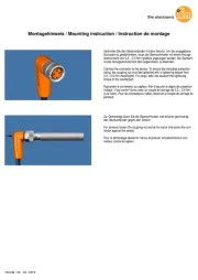
Montage
Nur die Sensorspitze darf in Zone 0 montiert werden; das End-
stück muß sich in Zone 1 oder 2 befinden.
Die Abdichtung an der Übergangsstelle muß nach den Bestim-
mungen des jeweiligen Einsatzfalles ausgelegt sein.
Die Sensorspitze sollte vollständig ins Medium hineinragen.
Montieren Sie das Gerät bei waagerecht verlaufenden Rohren mög-
lichst seitlich (Abb 2). Nicht direkt von oben oder unten.
Montieren Sie das Gerät bei senkrecht verlaufenden Rohren in der
Steigleitung (Medium strömt aufwärts, Abb. 3).
A = 15mm für Geräte mit Anschluß M12 x 1 und G 1/4,
A = 33mm für Geräte mit Anschluß G 1/2.
Um Fehlfunktionen zu vermei-
den, müssen Mindestabstände
zwischen Sensor und Krümmun-
gen, Ventilen u. ä. eingehalten
werden.
- Mindestens 5 mal Rohrdurch
messer an der Anströmseite.
- Mindestens 3 mal Rohrdurch
messer an der Abströmseite.
Elektrischer Anschluß:
Das Gerät darf nur von einer Elektrofachkraft installiert werden.
Befolgen Sie die nationalen und internationalen Vorschriften zur
Errichtung elektrotechnischer Anlagen.
Anschlußbelegung: siehe Montageanleitung zu Schaltverstärker
VS 0200Exi.
Wartung:
Der Strömungssensor ist in die wiederkehrende Druckprüfung des
Behälters bzw. der Rohrleitung einzubeziehen.
Montageanleitung
Installation Instructions
Notice de Montage
Strömungssensor
Flow sensor
Sonde de débit
SF (Ex)
Sachnr. 701038 / 01 09 / 99 Technische Änderungen behalten wir uns ohne vorherige Ankündigung vor. Papier chlorfrei
R
A
2
A
3
min.
5 x D
min.
3 x D
D
4
Dichtung
VS 0200Exi
1
Dichtung
Zone 0 Zone 1 oder 2 erhalb des Auß
Ex-Bereichs
Dichtung
27
15
102
12
56
27
M12x1
7,7
G2
1
12
4515
7,7
27
92
27
15
102
12
56
27
7,
7
G 4
1
SFR14
SFM12
SFR12

Functions and features
In conjunction with the VS0200 Exi control monitor the flow sensor
monitors flows in liquids and gases. The sensor / control monitor com-
bination senses whether there is a preset flow rate (= medium flowing)
or not (= medium not flowing) and provides a switched signal.
The sensor is designed to conform to the requirements of EN 50 014
and EN 50 020. In conjunction with the control monitor VS0200 Exi
the unit can be mounted in installations to zone 0 where explosive gas /
air or vapour / air mixtures at pressures between 0.8 and 1.1 bar and
temperatures of the mixture between -20°C and +60 C exist °
(PTB approval no. Ex-94.C.2029).
The explosion protection of the sensor depends on the tightness of the
sensor tip in particular. As a consequence the sensor can only be used
for combustible gases an liquids for which the chemical resistance and
the corrosion resistance of the sensor tip are sufficient.
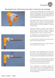
Installation
Only the sensor tip may be mounted in zone 0; the end part
must be in zone 1 or 2.
The sealing at the point of transition must conform to the regu-
lations governing each individual application.
Fonctionnement et caractéristiques
La sonde de d bit surveille en liaison avec le boé îtier lectroniqueé
VS0200 Exi la d bit de milieux liquides et gazeux. La combinaisoné
sonde-bo tier î électronique détecte si une valeur de circulation pré és -
lectionnée est atteinte (= liquide en débit) ou non (= liquide pas en
débit) et fournit un signal de commutation.
La sonde regroupe les exigences des normes EN 50 014 et EN 50 020.
En liaison avec le bo lectronique VS0200 Exi l appareil peut îtier é ’ être
monté dans de installations de la zone 0 où des mélanges explosifs
gaz/air ou vapeur/air sont pr des pressions entre 0,8 et 1,1 barésents à
et des temp lange entre -20 C et +60 C (no de homo-ératures du mé ° °
logation PTB Ex-94.C2029).
La protection du détecteur de circulation de fluides contre les explo-
sions d pend particuli rement de l de l de laé è ’imperm abilité é ’extr mité é
sonde.
Par cons quent le d tecteur ne peut tre utilis que pour les gaz et lesé é ê é
liquides combustibles pour lesquels la r sistance chimique et la ré ésis-
tance extr mità la corrosion de l’ é é de la sonde sont suffisantes.
Montage
Il faut monter que la partie sensible de la sonde dans la zone 0;
la partie oppos e doit se trouver dans la zone 1 ou 2.é
L’étanchéité du piquage doit être conforme aux règlements se
rapportant à l’ application.
La partie sensible de la sonde doit se trouver compl tement dans leè
fluide. Dans le cas des tubes horizontaux monter l'appareil latérale-
ment, si possible (fig. 2). Ne pas le monter directement d'en haut ou
d'en bas. Dans le cas des tubes verticaux nous recommandons d’ef-
fectuer le piquage là où le fluide monte (fig. 3).
A = 15 mm pour des appareils, filetage M12x1 et G1/4" (BSP).
A = 33 mm pour des appareils, filetage G1/2" (BSP).
Afin d viter un mauvais fonc-’é
tionnement une distance mini-
mum doit être respectée entre la
sonde et les coudes, vannes, etc.
- Min. 5 x diam tre de la canaliè
sation en amont,
- min. 3 x diamètre de la canali
sation en aval.
Raccordement électrique:
L'appareil doit tre mont par un ê é électricien.
Les r glements nationaux et internationaux relatifs l'installationè à
de mat lectrique doivent ériel é être respectés.
Sch tieréma de branchement: voir notice de montage pour le boî
électronique VS0200 Exi.
Entretien:
Le d tecteur de circulation de fluides doit tre inclus lors du contré ê ôle
de pression p riodique du r cipient ou des tubes.é é
The sensor tip must be completely immersed in the medium.
In the case of horizontal pipes mount the unit from the side, if possi-
ble (fig. 2). Do not mount it directly from the top or bottom.
In the case of vertical pipes mount the unit in a place where the medi-
um flows upwards (fig. 3).
A = 15mm for units with M12 x 1 and 1/4" thread
A = 33mm for units with 1/2" thread.
To avoid malfunction a minimum
distance between the flow moni-
tor and bends, valves or such like
must be observed.
- Min. 5 x pipe diameter upstream,
- min. 3 x pipe diameter down
stream.
Electrical connection:
The unit must only be connected by an electrician.
The national and international regulations for the installation of
electrical equipment must be observed.
Wiring: see installation Instructions for the control monitor
VS0200 Exi.
Maintainance:
The sensor must be included in the recurrent pressure tests of the
container or of the pipes.
A
2
A
3
min.
5 x D
min.
3 x D
D
4
sealing
VS 0200Exi
1
sealing
zone 0 zone 1 or 2 outside hazardous
area
sealing
A
2
A
3
min.
5 x D
min.
3 x D
D
4
joint
d’étanchéit
VS 0200Exi
1
joint
d’étanchéité
Zone 0 Zone 1 ou 2 en dehors de la
zone explosive
joint
d’étanchéit
Product specificaties
| Merk: | IFM |
| Categorie: | Niet gecategoriseerd |
| Model: | SF2210 |
Heb je hulp nodig?
Als je hulp nodig hebt met IFM SF2210 stel dan hieronder een vraag en andere gebruikers zullen je antwoorden
Handleiding Niet gecategoriseerd IFM
3 September 2025
3 September 2025
2 September 2025
27 Augustus 2025

15 Augustus 2025
15 Augustus 2025

15 Augustus 2025
15 Augustus 2025

15 Augustus 2025

14 Augustus 2025
Handleiding Niet gecategoriseerd
- Musicmate
- Maul
- GE
- Bravilor
- Casa Deco
- SeaLife
- Longvie
- JD Bug
- Vogels
- Robern
- Termozeta
- Nesco
- Amana
- Volkswagen
- Mars Gaming
Nieuwste handleidingen voor Niet gecategoriseerd

14 September 2025

14 September 2025

13 September 2025

13 September 2025

13 September 2025

13 September 2025

13 September 2025

13 September 2025

13 September 2025

13 September 2025